DIY Soldering Kit Infrared Remote Control Intelligent Car (10006476)
Check my rate
View locations
| Main centres: | 1-3 business days |
| Regional areas: | 3-4 business days |
| Remote areas: | 3-5 business days |
Product information
Introduction:
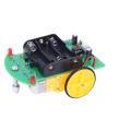
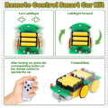
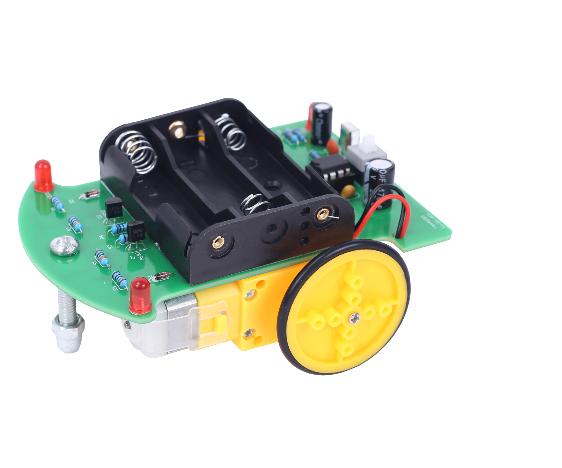
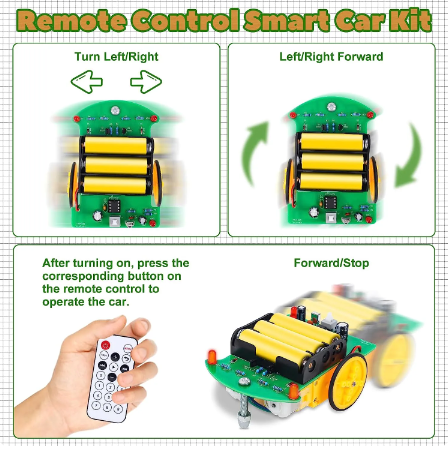
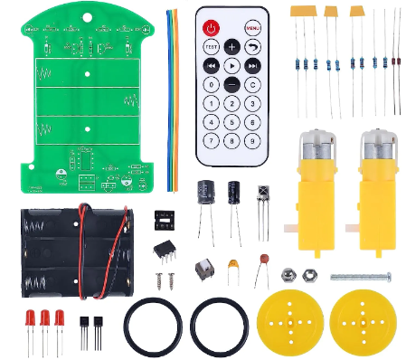
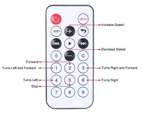
D2-4 is a Infrared Remote Control Intelligent Car DIY Kit. Users can control various operating states of the smart car through an infrared remote control, such as forward, turns left, turns right, stop, and also adjust the speed of movement.
Parameter:
1. Product Name: D2-4 Infrared Remote Control Intelligent Car DIY Kit
2. Work Voltage: DC 4.5V
3. Power Type: AA*3 Battery (NOT Included)
4. Work Current: <100mA
5. Work Temperature: -20~85
6. Work Humidity: 5%~85%RH
7. Size (Installed): 155*85*50mm
Note:
1. It is necessary to exchange the installation positions of the two wires of the motor if the car reverses after installation,
2. The motor can only run after pressing the remote control.
3. The motor should be as close to the edge of the PCB as possible to avoid affecting the installation of the wheels and causing them to get stuck by the PCB.
Installation Steps:
1. Step 1: Install 2pcs DO-35 1N4148Diode at D1, D2. Pay attention to the installation direction. There is a black mark on 1N4148and a white mark on PCB which are used to confirm the installation direction.
2. Step 2: Install 3pcs 1Kohm Metal Film Resistor at R5, R6, R9.
3. Step 3: Install 2pcs 10ohm Metal Film Resistor at R3, R4.
4. Step 4: Install 1pcs 220ohm Metal Film Resistor at R8.
5. Step 5: Install 1pcs 10Kohm Metal Film Resistor at R7.
6. Step 6: Install 2pcs 3.3Kohm Metal Film Resistor at R1, R2.
7. Step 7: Install 1pcs DIP-8 IC Socket at U1. There is a gap mark on one end of the IC Socket and there is a gap mark on PCB silk screen where the IC Socket can place on. These two marks are corresponding to each other and are used to specify the installation direction of the IC Socket.
8. Step 8: Install 1pcs 0.1uF 104 Ceramic Capacitor at C1.
9. Step 9: Install 1pcs 0.1uF 104 Monolithic Capacitor at C3.
10. Step 10: Install 2pcs TO-92S8550 Transistor atQ1,Q2. Pay attention to the installation direction.
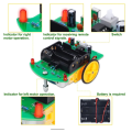
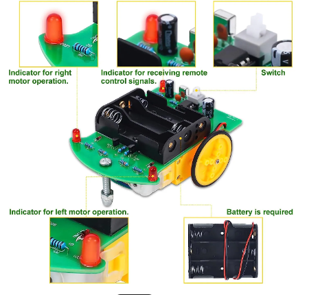
11. Step 11: Install 3pcs 5mm Red LED at LED1-LED3. Note: The longer pin is positive pole and connect to '+ 'pads which next to arc.
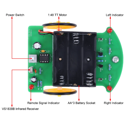
12. Step 12: Install 1pcs VS1838B Infrared Receiver at IR. Pay attention to the installation direction.
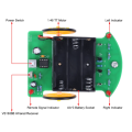
13. Step 13: Install 1pcs 8*8mm Self-locking Switch at S1. It is power switch.
14. Step 14: Install 1pcs 470uF Electrolytic Capacitor at C4. Note: The longer pin is positive pole and connect to '+ 'pads.
15. Step 15: Install 1pcs 100uF Electrolytic Capacitor at C2. Note: The longer pin is positive pole and connect to '+ 'pads.
16. Step 16: Install 1pcs DIP-8 IC STC15W104 Controller. There is a gap mark on one end of the IC and there is a gap mark on DIP-8 IC Socket where the IC can place on. These two marks are corresponding to each other and are used to specify the installation direction of the IC.
17. Step 17: Retain about 5cm wire and fix it on PCB by the double-sided tape on the back. Wires passing through PCB hole and Red connect to '+ 'pad.
18. Step 18: Install 10cm wires on 2pcs 1:48 TT Motor.
19. Step 19: Paste 2pcs motors onto the surface of the PCB. Note: The motor should be as close to the edge and front of the PCB as possible to avoid affecting the installation of the wheels and causing them to get stuck by the PCB.
20. Step 20: Connect 2pcs motor to MG1,MG2. Note: The wire near the PCB is connected to a square pad, and the other wire is connected to a circular pad.
21. Step 21: Install Black Rubber Tires on Yellow Rubber Wheel.
22. Step 22: Fix 2pcs Yellow Rubber Wheel on TT Motor by 2pcs M2.2*7mm Self Tapping Screw.
23. Step 23: Fix M5*35mm Screw by M5 Nut and M5 Nut Ball as front wheel of the car.