3pcs DIY IR Infrared Sensor Switch Kits  Infrared Proximity Switch Circuit Board Electronic Training 3pcs DIY IR Infrared Sensor Switch Kits  Infrared Proximity Switch Circuit Board Electronic Training 3pcs DIY IR Infrared Sensor Switch Kits  Infrared Proximity Switch Circuit Board Electronic Training 3pcs DIY IR Infrared Sensor Switch Kits  Infrared Proximity Switch Circuit Board Electronic Training 3pcs DIY IR Infrared Sensor Switch Kits  Infrared Proximity Switch Circuit Board Electronic Training 3pcs DIY IR Infrared Sensor Switch Kits  Infrared Proximity Switch Circuit Board Electronic Training 3pcs DIY IR Infrared Sensor Switch Kits  Infrared Proximity Switch Circuit Board Electronic Training 3pcs DIY IR Infrared Sensor Switch Kits  Infrared Proximity Switch Circuit Board Electronic Training 3pcs DIY IR Infrared Sensor Switch Kits  Infrared Proximity Switch Circuit Board Electronic Training 3pcs DIY IR Infrared Sensor Switch Kits  Infrared Proximity Switch Circuit Board Electronic Training
3pcs DIY IR Infrared Sensor Switch Kits  Infrared Proximity Switch Circuit Board Electronic Training 3pcs DIY IR Infrared Sensor Switch Kits  Infrared Proximity Switch Circuit Board Electronic Training 3pcs DIY IR Infrared Sensor Switch Kits  Infrared Proximity Switch Circuit Board Electronic Training 3pcs DIY IR Infrared Sensor Switch Kits  Infrared Proximity Switch Circuit Board Electronic Training
3pcs DIY IR Infrared Sensor Switch Kits  Infrared Proximity Switch Circuit Board Electronic Training
+6

3pcs DIY IR Infrared Sensor Switch Kits Infrared Proximity Switch Circuit Board Electronic Training

20 available / new
R478.00
Shipping
R35.00 Standard shipping using one of our trusted couriers applies to most areas in South Africa. Some areas may attract a R30.00 surcharge. This will be calculated at checkout if applicable.
Check my rate
The seller has indicated that they will usually have this item ready to ship within 12 business days. Shipping time depends on your delivery address. The most accurate delivery time will be calculated at checkout, but in general, the following shipping times apply:
 
Standard Delivery
Main centres:  1-3 business days
Regional areas: 3-4 business days
Remote areas: 3-5 business days
Seller
Buyer protection
Returns
Replacement Guarantee: 7 Days: We stand by this guarantee
Get it now, pay later

Product details

Condition
New
Location
International
Bob Shop ID
643364501
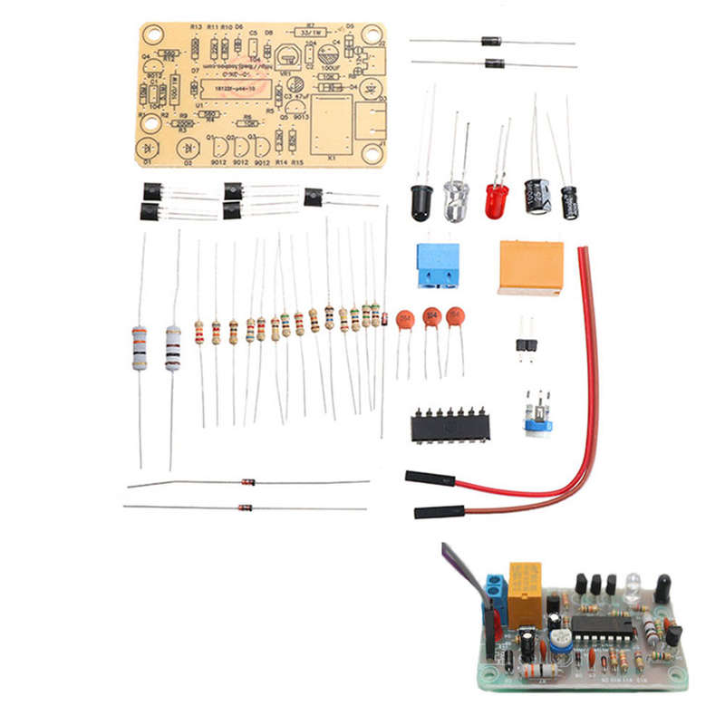
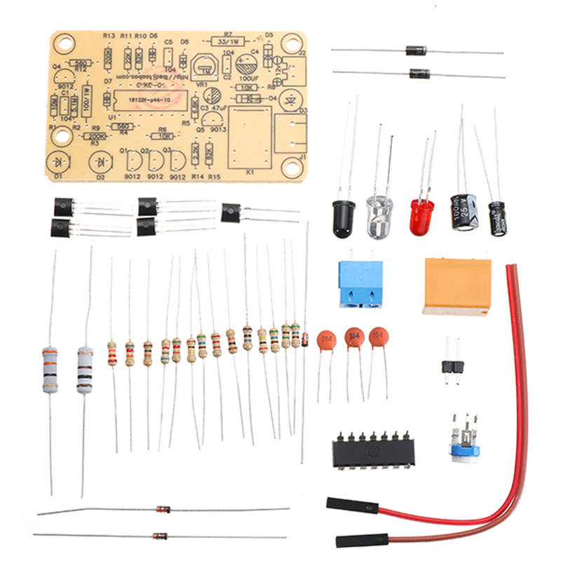
Parameter: Specifications: 35*60*1mm(length*width*thickness) Operating voltage: DC 12V 
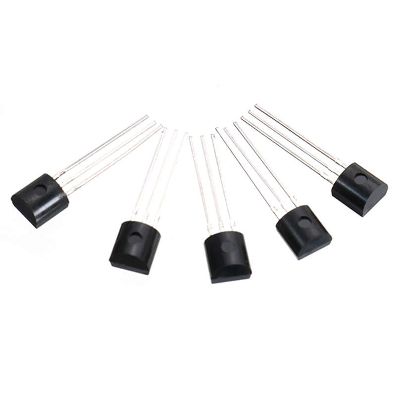
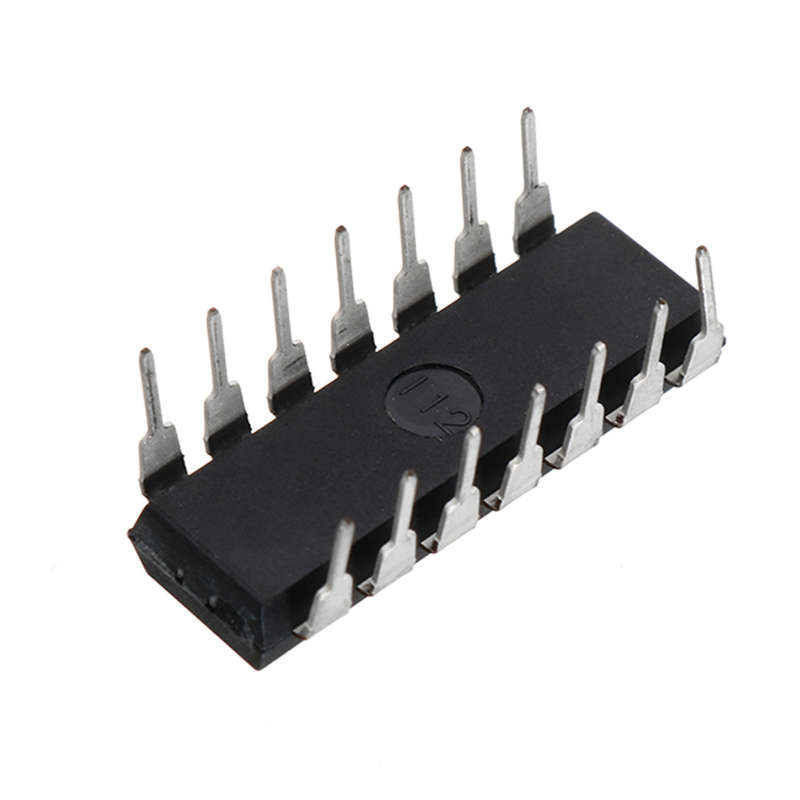
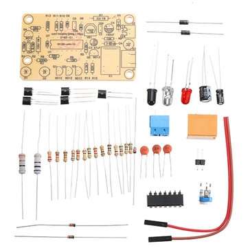
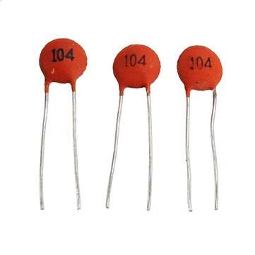
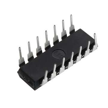
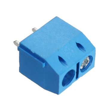
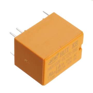
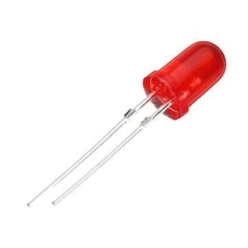
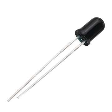
Welding step: 1. Solder 14 resistors, 2 diodes, 3 zener diodes. Do not solder in the wrong place; pay attention to the positive and negative electrodes when welding diodes, and use the negative electrode for the white side. It is recommended that the board be mounted tightly. 2. Next, when welding the HEF4093BP IC, do not solder the wrong direction. There is a U port on the IC, which corresponds to the silk screen on the PCB. Solder the transistor after welding the IC. Then welding electrolytic capacitors. 3. Then solder the adjustable resistor and three led lights to send infrared and black light to receive infrared. 4. Welded relays and sockets and 301-2P terminals. 
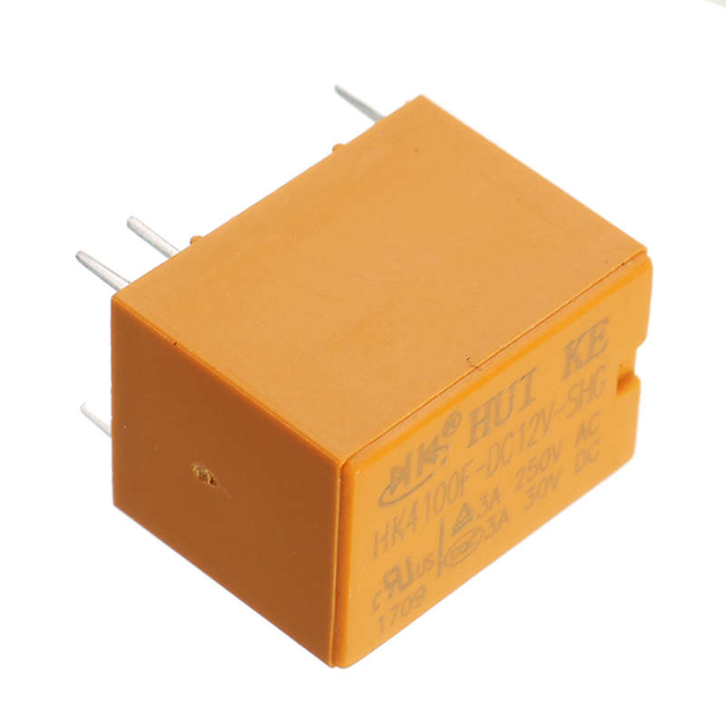
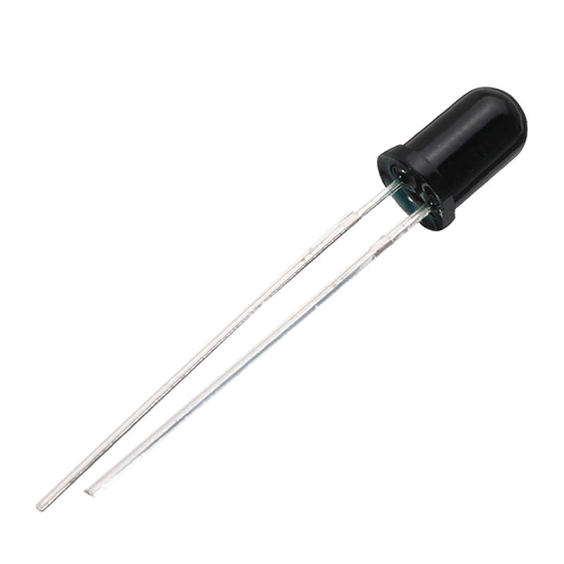
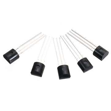
Circuit description: 1. Power circuit: input 12V power supply, DS can prevent reverse polarity of power supply, R7 is current-limiting current, C2, C4 filter. 2. Infrared sensing circuit: the oscillator is composed of UIC. R10, R1I1, D6, and cs. It outputs a pulse signal from pin 10 of U1. After being amplified by Q4, it drives the infrared emitting diode D2 to emit infrared signals to the space. If this signal is not blocked by an obstacle, the infrared receiver DI cannot receive the signal, so the follow-up circuit does not work. When there is an obstacle in front of the D2 (such as the hand shaking in front of the D2), the transmitted infrared signal is reflected back by the obstacle It will be received by DI. The received signal will be amplified by Q1 and Q2. Finally, the amplified infrared signal will be output at R3. The UIA will perform frequency selection and UID shaping to finally output at the 11-pin of U1. 3. Delay circuit: RS, VR1, C3 constitute a delay circuit, adjust the VRI can adjust the delay time after each action, the circuit design delay time adjustable in the range of 0-40$. (because the component has a certain error, the actual delay will be slightly different). 4. Switch control circuit: Q3, QS, K1 constitute the switch control circuit. If DI receives the signal, it will finally output the low-level control signal after the delay at the 4th pin of the UI, so that Q3, Qs will be turned on and K1 will be closed. D3 is the relay operating status indicator. Package included: 3 x DIY IR Infrared Sensor Switch Kits


Add to cart

Recently viewed

See more
Car Inlet Air Temperature Temperature Sensor Ambient Temperature Sensor 89424-60010 for
R431.00
Weeding Tools
R549.00 No bids
The SS ~ The Third Reich - Editors of Time-Life Books
R99.00
Hisense Front Loader Washing Machine Interlock Switch
R758.76

Similar products

3Pcs DIY Infrared Laser Aiming Anti-theft Burglar Alarm Module Kit
R550.00
DIY IR Infrared Sensor Switch Kits Infrared Proximity Switch Circuit Board Electronic Training Kits
R377.00
5pcs DIY Electronic Clapping Voice Control Switch Module Kit Induction Training DIY Production Kit
R427.00
3pcs DIY Silicon Controlled Switch Dimmer Lamp Kit Electronic Switch Module Kit
R345.00