
+4


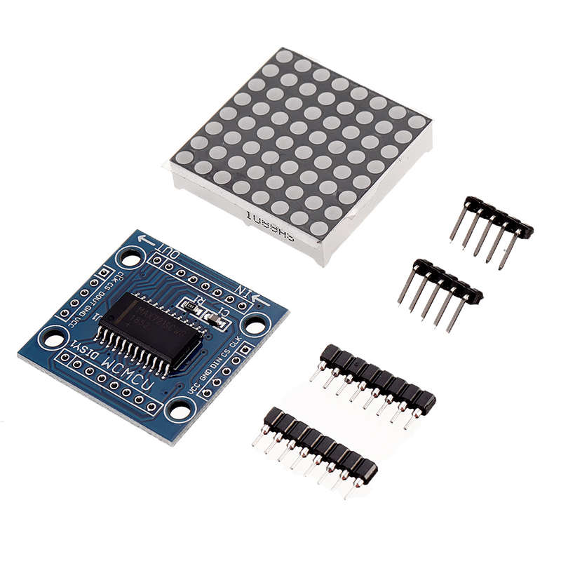
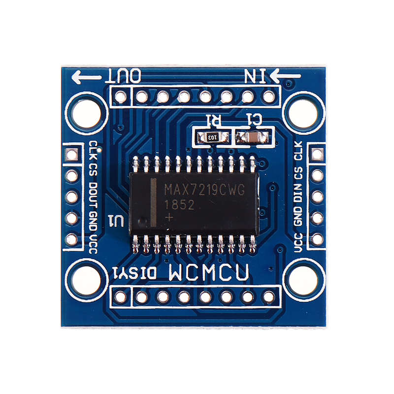
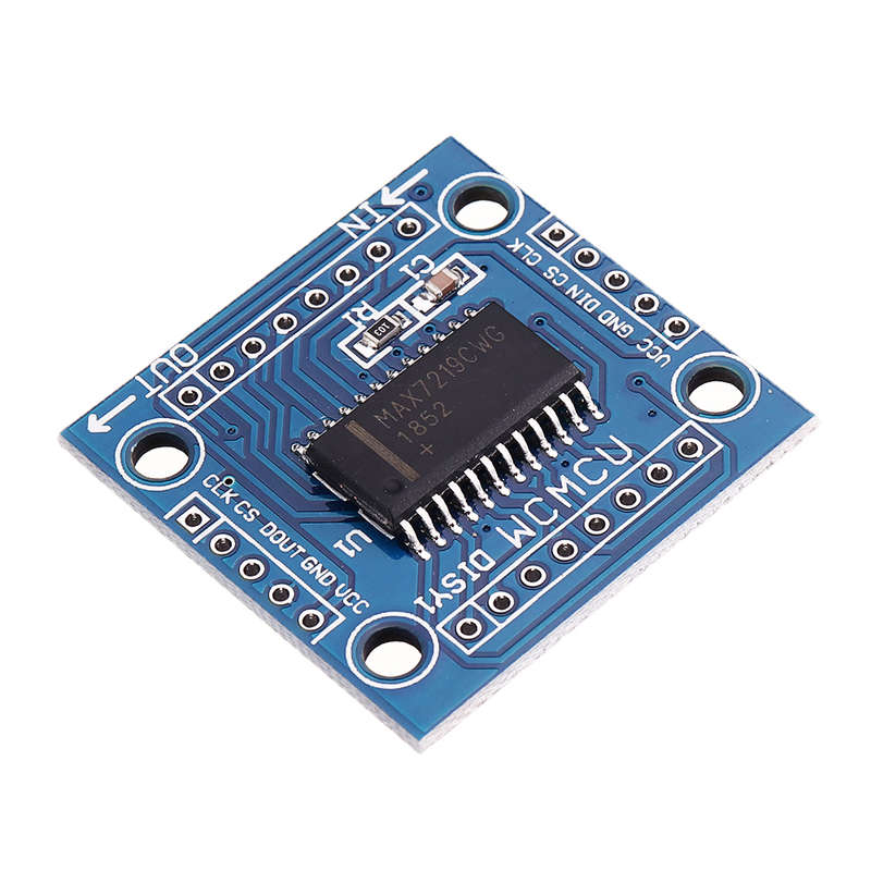
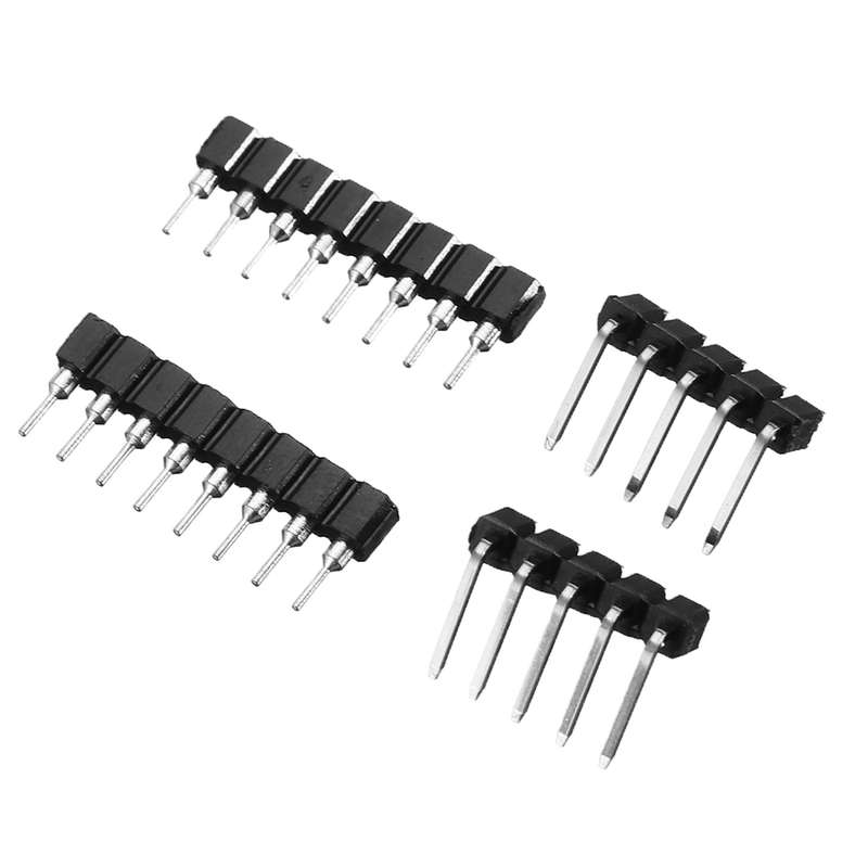
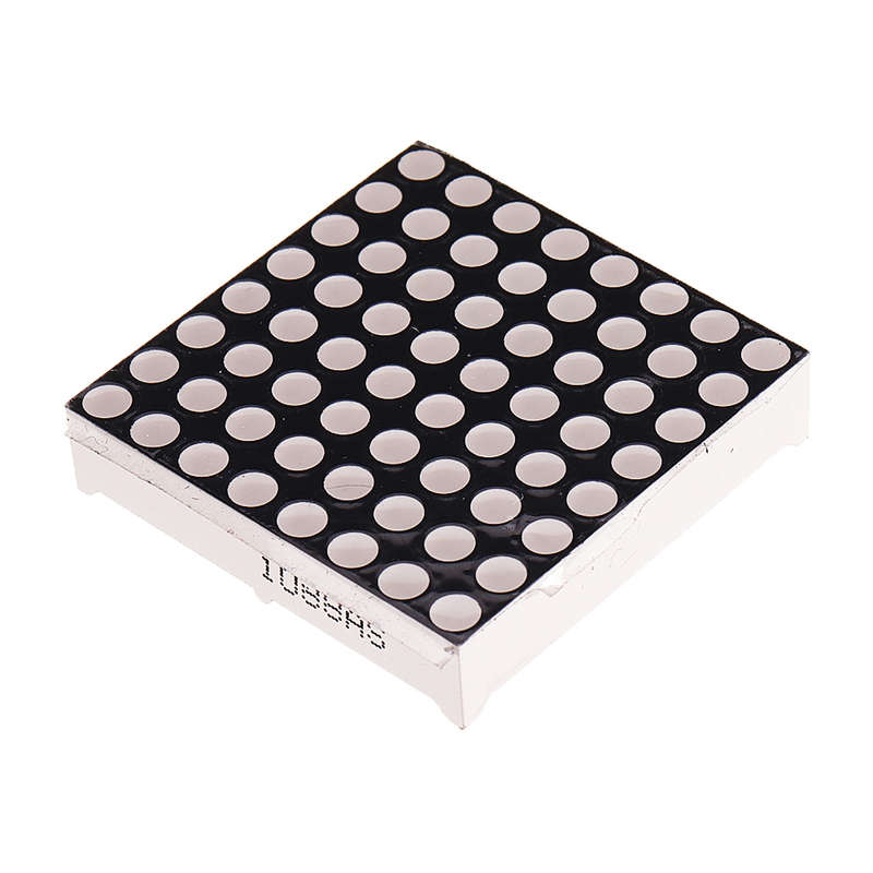
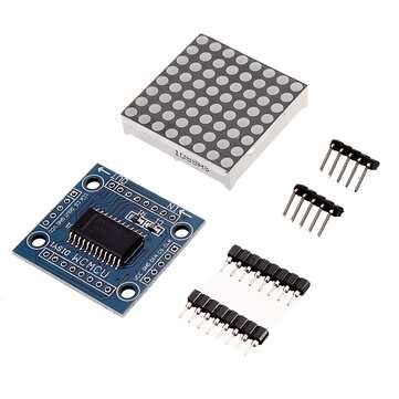
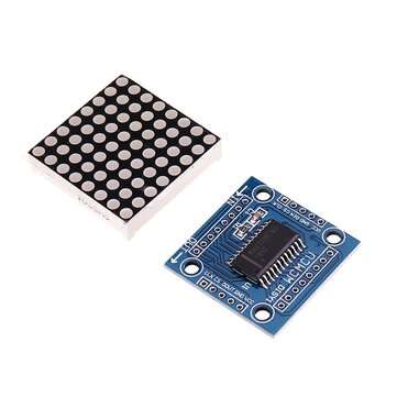
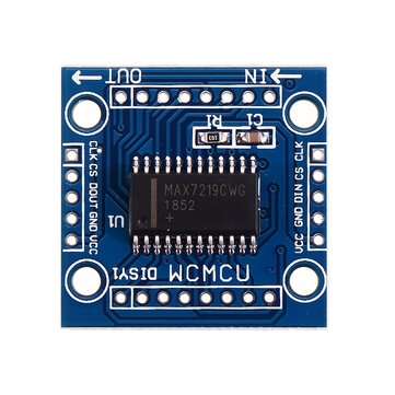
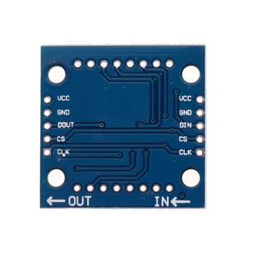
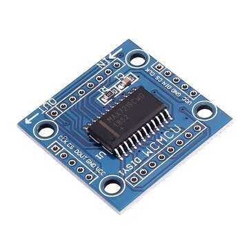
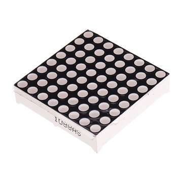
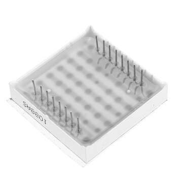
3Pcs MAX7219 Dot Matrix Module Microcontroller LED Module Display Module MAX7219 DIY Kit
20 available / new
Shipping
R35.00 Standard shipping using one of our trusted couriers applies to most areas in South Africa. Some areas may attract a R30.00 surcharge. This will be calculated at checkout if applicable.
Check my rate
Check my rate
The seller has indicated that they will usually have this item
ready to ship within 12 business days.
Shipping time depends on your delivery address.
The most accurate delivery time will be calculated at checkout,
but in general, the following shipping times apply:
Standard Delivery
| Main centres: | 1-3 business days |
| Regional areas: | 3-4 business days |
| Remote areas: | 3-5 business days |
Seller
Buyer protection
Returns
Get it now, pay later