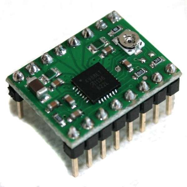
The A4988 is a carrier board or breakout board for Allegro's A4988 DMOS Microstepping Driver with Translator and Overcurrent Protection; we therefore recommend careful reading of the A4988 datasheet before using the driver. This stepper motor driver lets you control one bipolar stepper motor at up to 2 A output current per coil.
Features:
- Simple step and direction control interface
- Five different step resolutions: full-step, half-step, quarter-step, eighth-step, and sixteenth-step
- Adjustable current control lets you set the maximum current output with a potentiometer, which lets you use voltages above your stepper motor's rated voltage to achieve higher step rates
- Intelligent chopping control that automatically selects the correct current decay mode (fast decay or slow decay)
- Over-temperature thermal shutdown, under-voltage lockout, and crossover-current protection
- Short-to-ground and shorted-load protection
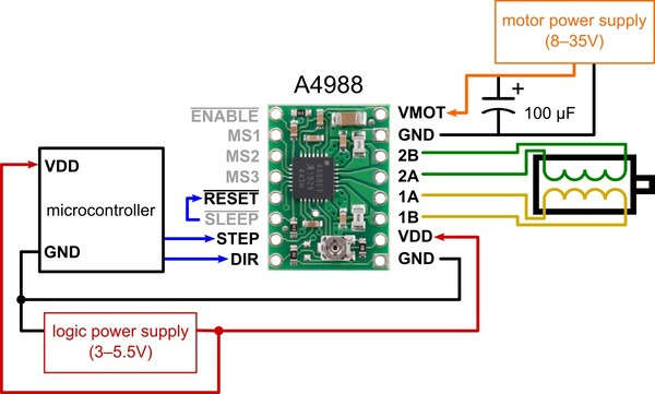
Power connections
The driver requires a logic supply voltage (3 — 5.5 V) to be connected across the VDD and GND pins and a motor supply voltage (8 — 35 V) to be connected across VMOT and GND. These supplies should have appropriate decoupling capacitors close to the board, and they should be capable of delivering the expected currents (peaks up to 4 A for the motor supply).
Warning: This carrier board uses low-ESR ceramic capacitors, which makes it susceptible to destructive LC voltage spikes, especially when using power leads longer than a few inches.
Under the right conditions, these spikes can exceed the 35 V maximum voltage rating for the A4988 and permanently damage the board, even when the motor supply voltage is as low as 12 V.
One way to protect the driver from such spikes is to put a large (at least 47 F) electrolytic capacitor across motor power (VMOT) and ground somewhere close to the board.
Motor connections
Four, six, and eight-wire stepper motors can be driven by the A4988 if they are properly connected.
Warning: This carrier board uses low-ESR ceramic capacitors, which makes it susceptible to destructive LC voltage spikes, especially when using power leads longer than a few inches.
Under the right conditions, these spikes can exceed the 35 V maximum voltage rating for the A4988 and permanently damage the board, even when the motor supply voltage is as low as 12 V.
One way to protect the driver from such spikes is to put a large (at least 47 F) electrolytic capacitor across motor power (VMOT) and ground somewhere close to the board.
Warning: Connecting or disconnecting a stepper motor while the driver is powered can destroy the driver.
(More generally, rewiring anything while it is powered is dangerous.)