| Main centres: | 1-3 business days |
| Regional areas: | 3-4 business days |
| Remote areas: | 3-5 business days |
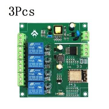
Specifications:
Model: LC-Relay-ESP12-1R-D8
Color: Blue
Material: PCB
Work Voltage:DC8-80V/USB5V
WIFI IC: ESP8266
Communication Protocol:UART
Load Voltatge:AC 250V or DC 30V(Max)
Load Current:10A(Max)
Work Temperature:-25~85
Work Humidity:5%~95%RH
Features:
1. Onboard mature and stable ESP-12F WIFI module, large capacity 4M BYTE FLASH;
2. All I/O ports and UART program download ports of the WIFI module are led out to facilitate secondary development;
3. Support DC8-80V/USB5V/pin header power supply;
4. Onboard WIFI module RST reset button;
5. ESP-12F supports the use of development tools such as ECLIPSE/ARDUINOIDE, and provides reference programs under the ARDUINOs' development environment;
6. Onboard one 5V relay, output switch signal, suitable for controlling loads with working voltage within AC 250V/DC30V;
7. Onboard power indicator, 1 programmable LED and relay indicator.
Package includes:
1 x DC 5-80V ESP8266 WiFi Single Channel Relay Module
GPIO output port introduction:
| No. | Name | Function Description | No. | Name | Function Description |
| 1 | GND | Power ground | 13 | IO10 | GPIO10 |
| 2 | Relay | Relay drive port, IO5 is used as the default drive. If you want to use other I/O to drive the relay, you can remove R14 and then connect the I/O driving the relay to this Relay pin. | 14 | MISO | Slave output Master input |
| 3 | IO2 | GPIO2; UART1_TXD | 15 | IO13 | GPIO13; HSPI_M0SI; UART0_CTS |
| 4 | IO4 | GPIO4 | 16 | IO14 | GPIO14; HSPI_CLK |
| 5 | RX | UART0_RXD; GPIO3 | 17 | ADC | A/D conversion result. Input voltage range 0~1V, value range: 0~1024 |
| 6 | 3V3 | 3.3V power supply | 18 | 3V3 | 3.3V power supply |
| 7 | SCLK | Clock | 19 | M0SI | Host output Slave input |
| 8 | IO15 | GPIO15; MTDO; HSPICS; UARTO_RTS | 20 | IO9 | GPIO9 |
| 9 | IO0 | GPIO0 | 21 | CS0 | Chip select |
| 10 | IO5 | GPIO5 | 22 | IO12 | GPIO12; HSPI_MISO |
| 11 | TX | UART0_TXD; GPIO1 | 23 | IO16 | GPIO16 |
| 12 | 5V | 5V power supply | 24 | GND | Power ground |
Port Locations:
VCC, GND: DC8-80V power supply
MICRO USB: DC5V USB power supply
Note: You can choose any of the three power supply methods: DC8-80V/DC5V USB/pin header 5V
6X6MM button: ESP8266 reset button
UART program download port: ESP8266's GND, RX, TX, 5V are connected to the GND, TX, RX, 5V of the external TTL serial port module respectively. When downloading, I0O needs to be connected to GND. After the download is completed, disconnect the connection between IO0 and GND.
GPIO pin header lead port
Relay output terminal
NC: Normally closed terminal, short-circuited with COM before the relay is energized, and left floating after energization;
COM: Common terminal;
NO: Normally open terminal, left floating before the relay is e