| Main centres: | 1-3 business days |
| Regional areas: | 3-4 business days |
| Remote areas: | 3-5 business days |
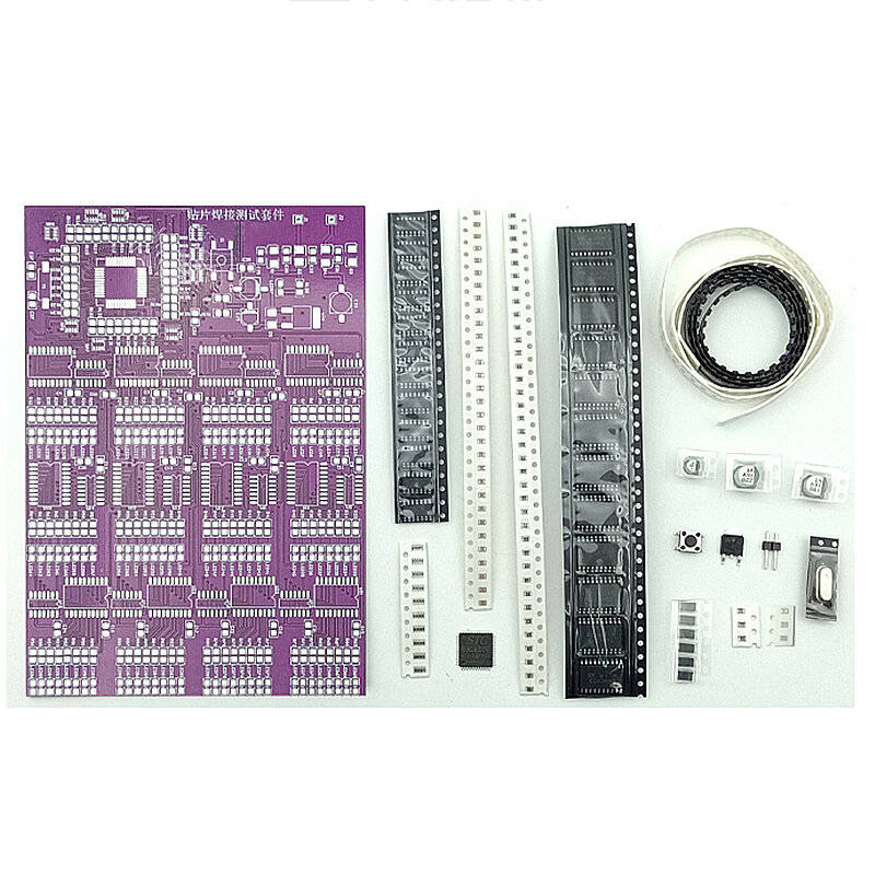
| S.N. | Name | Mark | Num. | Location |
| 1 | 103 capacitor0805 | 30 | C1-C24,C26, C29-C32, C35 | |
| 2 | 20P 0805 | 2 | C27, C37 | |
| 3 | 10uf/16V | 1 | C25 | |
| 4 | 100uf/16V | 1 | C34 | |
| 5 | 220uf/16V | 1 | C33 | |
| 6 | The resistance value of the resistor is between 1K-3K ohms | 102 | 101 | R1-R97, R123,R124,R135 |
| 7 | The resistance value of the resistor is between 0-100 ohms | 101 | 35 | R98-R106,R108-R122,R125-R134 |
| 8 | The resistance value of the resistor is between 8.5K-20K ohms | 203 | 1 | R107 |
| 9 | 10K exclusion | 103 | 9 | RP1-RP9 |
| 10 | IN4007 diode | 5 | D1-D5 | |
| 11 | LED light | 97 | LED1-LED97 | |
| 12 | 78M05 | 1 | U26 | |
| 13 | Touch the button | 1 | S1 |