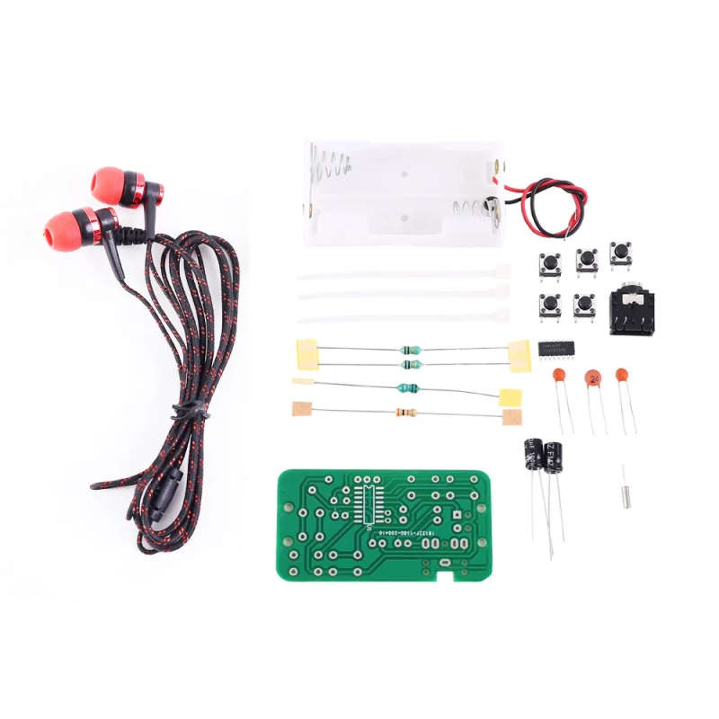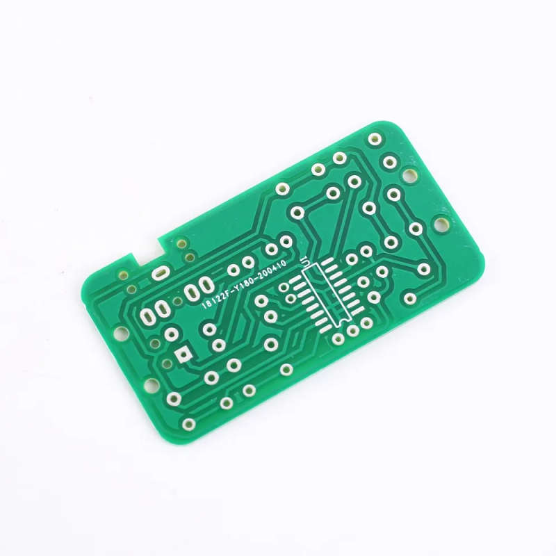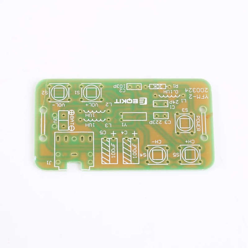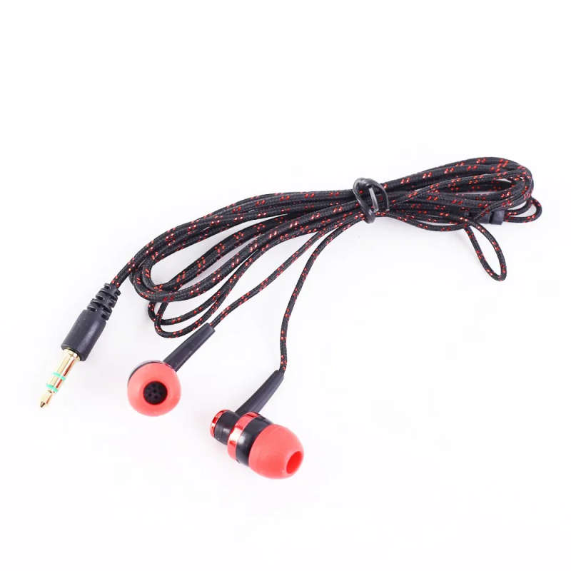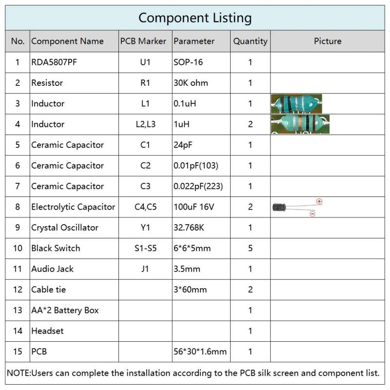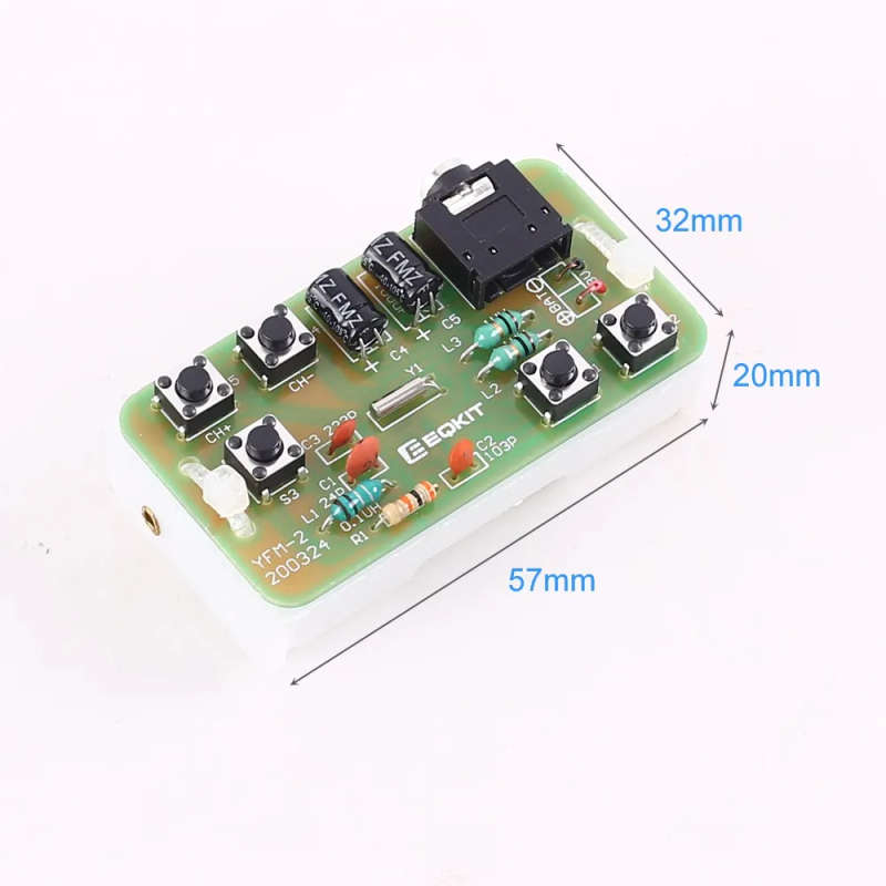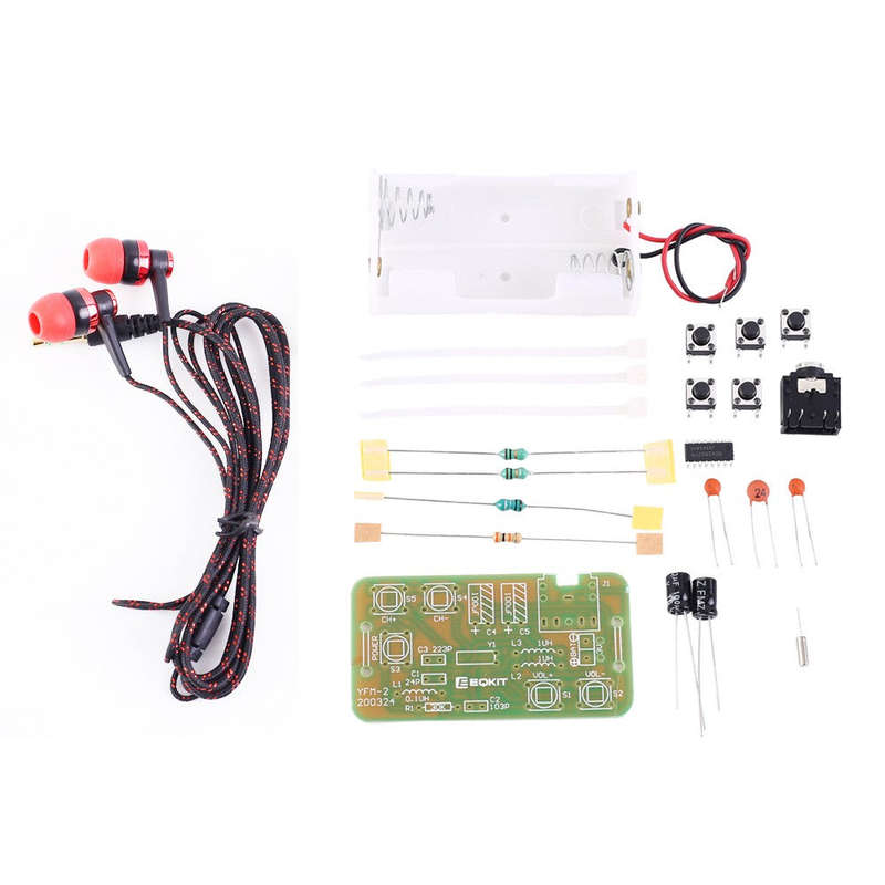

DIY FM Stereo Radio Module with Headset - Adjustable 76-108MHz Wireless Receiver DC 3V
2 available / new
Only 2 left – grab it before it’s gone!
Shipping
R35.00 Standard shipping using one of our trusted couriers applies to most areas in South Africa. Some areas may attract a R30.00 surcharge. This will be calculated at checkout if applicable.
Check my rate
Check my rate
There are various locker and counter collection points across South Africa.
View locations
View locations
The seller has indicated that they will usually have this item
ready to ship within 3 business days.
Shipping time depends on your delivery address.
The most accurate delivery time will be calculated at checkout,
but in general, the following shipping times apply:
Standard Delivery
| Main centres: | 1-3 business days |
| Regional areas: | 3-4 business days |
| Remote areas: | 3-5 business days |
Seller
Buyer protection
Get it now, pay later