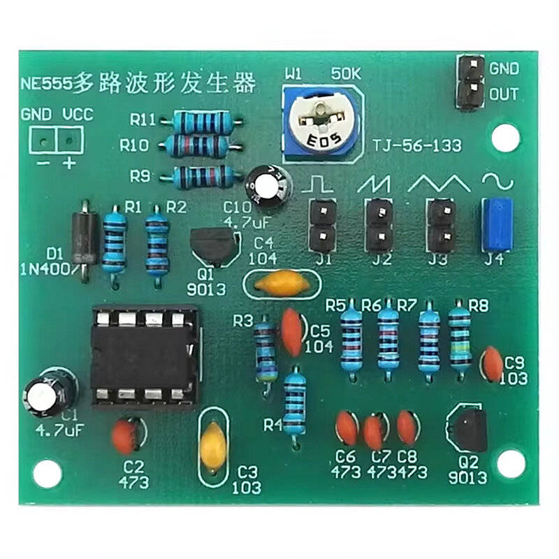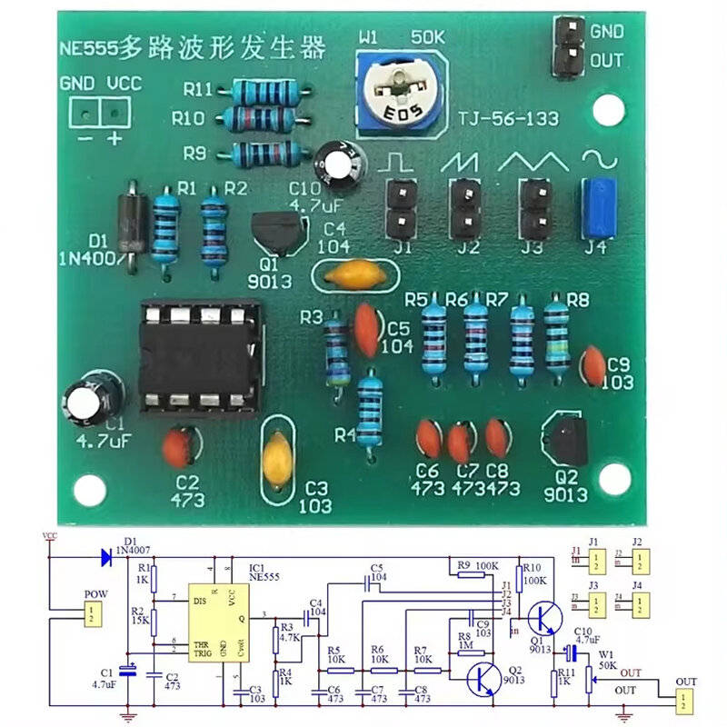


DIY Sine Triangle Square Wave NE555 Multi-Channel Waveform Generator Module Kit
Check my rate
View locations
| Main centres: | 1-3 business days |
| Regional areas: | 3-4 business days |
| Remote areas: | 3-5 business days |


| Main centres: | 1-3 business days |
| Regional areas: | 3-4 business days |
| Remote areas: | 3-5 business days |
Description:
In the circuit, D1 is the anti-power diode, and C1 is the filter capacitor. IC1, R1, R2 and C2 form a square wave generator. The signal is output from the three pins of IC1, and C3 is the anti-interference capacitance.
The square wave output from the third pin of IC1 is coupled through R3, R4 partial voltage and C5, and the square wave can be output at the output end by shorting J1 with a short circuit block. The other circuit passes through C4 coupling and C3 partial pressure
The sawtooth waveform formed by the integration circuit R5 and C7 is output by J2, and then the triangle wave formed by the integration circuit R6 and C8 is output from J3. After R7, C9, R8, Q2
After the amplification circuit composed of R9 is amplified, the Q2 collector becomes a sine wave.
R10, R11 and Q1 form an emitter following amplifier circuit, and the