
| Main centres: | 1-3 business days |
| Regional areas: | 3-4 business days |
| Remote areas: | 3-5 business days |
Pay before 9am and courier will deliver same day in Jhb. Weekdays only.
All deliveries are made nationally, within South Africa only.
Items are dispatched with 24 Hours after online purchase and are delivered within 3-5 working days.
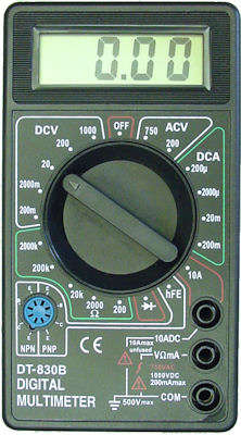
The DT830B digital multimeter is a compact, light tool - a bargain if you need something cheap and reliable. The heart of the instrument is the ICL7106 IC coupled with a large 3 1/2 digit, 7 segment, 0.5" high LCD display with a maximum reading of 1999.
The DT-830B can measure DCV (0,1mV - 1000V), ACV (0,1V - 750V), DCA (0,1mA - 10A), Ohm (0,1Ω - 2MΩ) diode forward voltage drop and hFE for bipolar PNP and NPN transistors.
Operating instructions
- Connect the red lead to "VΩmA" jack and the black test lead to the "COM" jack.
- Set the rotary switch at the desired V~ position.
- Connect the test leads across the source or load being you want to measure and read the voltage value on the LCD display.
- Connect the red test lead to the "VΩmA” jack and the black test lead to the "COM” jack.
- Set the rotary switch at the desired position. If the voltage to be measured is not known, set the range switch at the highest range position and then reduce it until a satisfactory resolution is obtained.
- Connect the test leads across the source or load being measured. Read the voltage value and polarity on the LCD display.
- Connect the red test lead to the "VΩmA” jack and the black lead to the "COM” jack. For measuring currents between 200mA and 10A, insert the red lead into the "10A” (unfused) jack.
- Set the rotary switch at desired position.
- Open the circuit in which the current is to be measured, and connect test leads in series with the circuit.
- Read the current value on the LCD display along with the polarity of red lead connection.
- Connect the red test lead to "VΩmA” jack and the black lead to "COM” jack. The polarity of red lead is positive "+” in this mode.
- Set the rotary switch at desired range position.
- Connect the test leads across the resistance to be measured and read the LCD display.
Note: If the resistor being measured is connected to a circuit, turn off power and discharge all capacitors before applying measurements!
Before attempting to insert transistors into the socket for testing, always be sure that test leads have been disconnected from any measurement circuits. Also, components should not be connected to the hFE socket when making voltage measurements with the test leads!
Diode test
- Connect the red test lead to "VΩmA” jack and the black lead to the "COM” jack. The polarity of red lead is positive "+”.
- Set the rotary switch at the diode test position.
- Connect the red lead to the anode of the diode to be tested and the black lead to the cathode of the diode.
- The forward voltage drop of the diode will be displayed in mV. If the connection is reversed, only figure "1” should be displayed for a good diode.
Specifications
The DT830B has a wide operating temperature: -20°C to 75° (32°F to 104°F) and a storage temperature of: -10°C to 50°C (10°F to 122°F). The accuracy is guaranteed to stay in the following limits for 1 year, when used at 23°C ± 5°C, less than 75% relative humidity:
Frequency range: 45Hz to 450Hz.
Response: Average responding, calibrated in RMS of a sine wave.
| Range | Resolution | Accuracy |
|---|---|---|
| 200V | 100mV | ±1.2 % of rdg ± 10 digits |
| 750V | 1V | ±1.2 % of rdg ± 10 digits |
Note: some models have a maximum input voltage of only 600V AC with an overload protection of 600V DC or RMS AC for all ACV ranges.
| Range | Resolution | Accuracy |
|---|---|---|
| 200mV | 0.1mV | ±0.5% of rdg ± 2 digits |
| 2000mV | 1mV | ±0.5% of rdg ± 2 digits |
| 20V | 10mV | ±0.5% of rdg ± 2 digits |
| 200V | 100mV | ±0.5% of rdg ± 2 digits |
| 1000V | 1V | ±0.8% of rdg ± 2 digits |
Overload protection: F250mA 250V fuse (10A range is unfused!).
| Range | Resolution | Accuracy |
|---|---|---|
| 200µA | 0.1µA | ±1.0% of rdg ± 2 digits |
| 2000µA | 1µA | ±1.0% of rdg ± 2 digits |
| 20mA | 0.01mA | ±1.0% of rdg ± 2 digits |
| 200mA | 0.1mA | ±1.5% of rdg ± 2 digits |
| 10A | 10mA | ±3.0% of rdg ± 2 digits |
Maximum open circuit voltage: 3.2V
Overload protection: 250V rms. AC on all ranges.
| Range | Resolution | Accuracy |
|---|---|---|
| 200Ω | 0.1Ω | ±0.8% of rdg ± 3 digits |
| 2000Ω | 1Ω | ±0.8% of rdg ± 2 digits |
| 20kΩ | 10Ω | ±0.8% of rdg ± 2 digits |
| 200kΩ | 100Ω | ±0.8% of rdg ± 2 digits |
| 2000kΩ | 1kΩ | ±1.0% of rdg ± 2 digits |
Diode aprox. testing voltage is 2.8V with a current of 1mA. The overload protection in the diode test mode is 250V RMS. AC.
Over range indication: figure "1" on the display.
Size: 126×70×25mm
Weight: 170g.

Image is for illustrative purpose only and might differ from actual. Shown.