Package weight: 0.01 kgFeature:
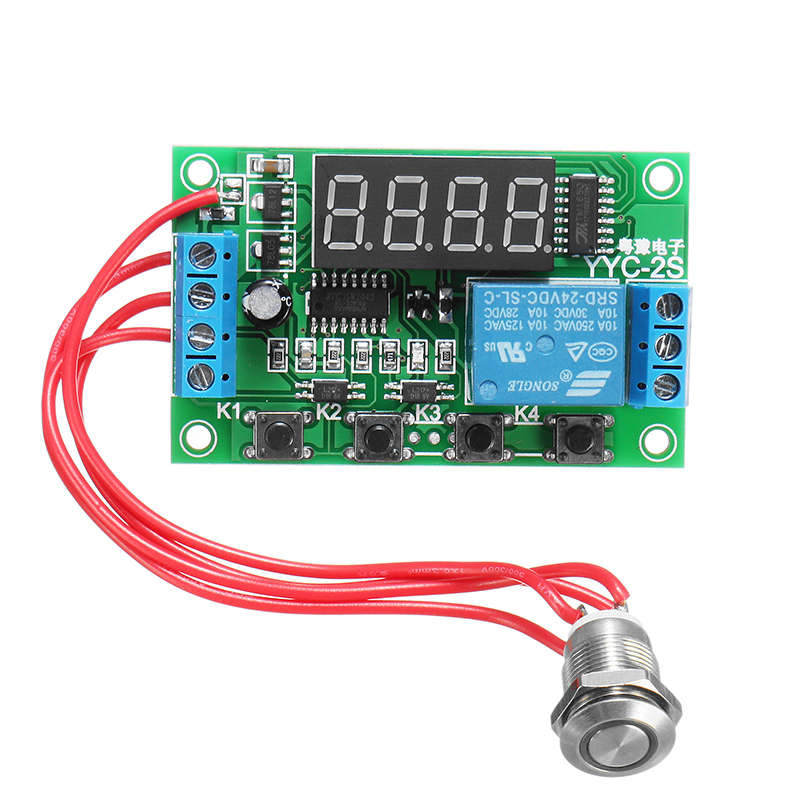
Model: YYC-2S 24 kinds of commonly used functions; can control the solenoid valve, water pump, motor, lights, etc.
Input voltage: DC 5/6/12/24V optional
Output power: can control the DC within 5A or AC load
Time range: 0.01 seconds ~ 999 minutes adjustable at any time
Terminal Description:
1. DC +: Input positive DC power supply
2. DC -: Input negative DC power supply
3. IN +: Signal input positive
4. IN -: Signal input negative
5. NO: Normally open relay interface, the relay hanging before pull-in, after pulled shorted connect to COM
6. COM: Relay Common Interface
7. NC: Normally closed relay interface, the relay is shorted connect to COM before pull-in, after pulled hanging
Function list:
P-11: Jog (offer signal to relay pull-in, the signal disappears, the relay stop)
P-12: Self-locking (offer signal to pull, give a signal again to stop relay)
P-13: Offer signal, the relay will stop automatically for A second; trigger will be invalid during the delay time
P-14: Offer signal, the relay will stop automatically for A second; trigger re-timing during the delay time
P-15: Offer signal, the relay will stop automatically for A second; trigger superimposed during the delay time
P-16: Offer signal, the relay will stop automatically for A second; trigger reset during the delay time
P-17: Offer signal, relay pull-in, input signal is disconnected, start counting time after A second power off, during the delay period offer signal again to keep output, timing stop
P-18: When power is on, the relay will pull in immediately and power will be off after A second delay; until the next power-on
P-21: Offer signal, delay A seconds, the relay pull
P-22: Offer signal, more than A seconds, the relay pull, the signal disappears, the relay stops
P-23: After the signal disappears for more than A second, the relay will be closed, the signal will disappear and the relay will stop
P-24: When the signal exceeds A second, the relay will be closed and the relay will stop after the signal disappears for more than A seconds
P-25: When the signal exceeds A second, the relay will pull in. If the signal exceeds A seconds again, the relay will stop
P-26: When the signal pull exceeds A second and stop, signal disappear and relay pull again, after A second stop
P-27: Detection of pulse signal, the relay stops; no pulse signal, the relay delay A seconds then pull; (continuous signal or signal disappear are regarded as no pulse signal)
P-28: After power on, after a second delay, the relay will be pulled until it is powered off
P-31: After power on, relay pull A seconds, off B seconds, infinite loop; power off to stop
P-32: With signal, start P-31 infinite loop; signal disappears, terminates loop
P-33: Give a signal, start P-31 infinite loop; give a signal again to terminate the loop
P-34: After the power on, the relay will pull in after A second delay and will stop after B seconds
P-35: With signal, delay A seconds later, the relay pull, after pull B seconds stop
P-36: With signal, more than A seconds, the relay pull, after pull B seconds the relay stop, the signal disappears, the timer cleared to stop
P-37: With signal, the relay automatically stop A seconds, and then timing B seconds again, duiring A + B signal trigger is invalid
P-38: With signal, the relay pull A seconds automatically stop, stop re-time after B seconds, again pull A seconds to automatically stop
Key Settings Description:
Power display "----" means to enter standby mode
Press the first K1, (more than 1 second effect to prevent false triggering) Display: P -11: K2 adjust the main mode, K3, K4 adjustment function
Press the second K1, the screen displays: A001: K2 and K3 adjust the first time A, K4 adjust the decimal point (time unit)
Press the third K1, the screen displays: B001: K2 and K3 adjust the second time B, K4 adjust the decimal point (time unit)
Press the fourth K1, "----" indicates that the standby state
Press K4 in standby mode to permanently turn off / on the display and switch to low power mode
Decimal point time unit Description:
X.XX timing range: 0.01 seconds to 9.99 seconds
XX.X timing range: 0.1 seconds to 99.9 seconds
XXX timing range: 1 second to 999 seconds
XXX. timing range: 1 minute ~ 999 minutes
Package includes:
1 x External Trigger Delay Switch Module