

| Main centres: | 1-3 business days |
| Regional areas: | 3-4 business days |
| Remote areas: | 3-5 business days |
Flashing Blinking LED Flip Flop DIY Simple Flash Astable Multivibrator Circuit
This circuit is commonly called a Flashing LED or Blinking LED and has the technical name FLIP FLOP or ASTABLE MULTIVIBRATOR.
It uses two transistors to alternately flash two LEDs and will operate from 3v to 9v.
Principle of Operation
There will be a slight difference between the gain (the ability to amplify) of the two transistors, Q1 and Q2 and one of them will turn on faster to start the circuit flashing. If Q1 turns on first, the voltage on the collector will be very near to 0v and D1 will illuminate. At the same time the positive lead of C1 will be at about 0v and the negative lead will also be about 0v. This will put 0v on the base of Q2 and Q2 will be turned off. This means LED D2 will not be illuminated.
C1 will gradually charge (in the opposite direction to its polarity) via 10k resistor R2 and when the base of Q2 see a voltage of about 0.65v, it will start to turn ON.
This will reduce the voltage on the collector of Q2 and make the positive lead of C2 drop. This will cause the negative lead of C2 to drop also and reduce the voltage on the base of Q1. This will start to turn off Q1 and the voltage on the collector will rise.
This will further increase the voltage on the base of Q2 and it will turn on more.
This action is called REGENERATIVE ACTION as one transistor will turn off and cause the other to turn on. This occurs very quickly and the two transistors swap states. This means the second LED illuminates and the first LED is not illuminated.
The flashing frequency depends on the value of C1, C2, R2 and R3.
Assembly
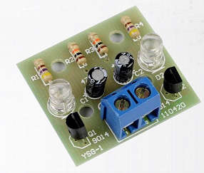
Fit one component and splay the legs slightly so it doesn't fall out of the holes. Turn the board over and hold the soldering iron on one side of the lead and the solder on the other side. The solder will melt and flow across to the iron. This will take less than one second.
Snip the leads close to the solder-joint. Solder one component at a time. All the components must be fitted around the correct way, and there is only one way to fit them. However the 4 resistors can be fitted around either way as they are classified as a "non-polar component." The longer leg of the LED is the positive (+) side, this also applies to the two capacitors. The two 10k resistors are in the centre and the two 470 ohm resistors are at the edges of the board. Connect a 3v to 9v supply to the 2-terminal connector with the positive on the left and the negative on the right. The circuit will not be damaged if the supply is reversed, but it will not work.
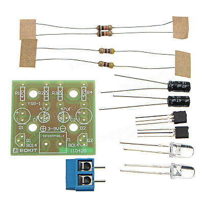
Components
Resistors - 470Ω x 2 (R1 and R4)
Resistors - 10KΩ x 2 (R2 and R3)
Capacitors - 47uF 16V x 2 (C1 and C2)
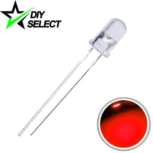
LED - 5mm Red x 2 (D1 and D2) If you want a different colour, please let us know.
Triode - 9014 x 2 (Q1 and Q2)
Terninal - 2P x 1 (J1)
PCB - FR4 x 1 (28 x 30mm)


This item is available in stock and is not drop shipped. This avoids delays, customs and extra VAT.