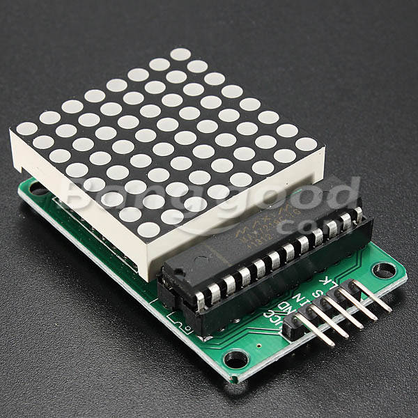
MAX7219 Dot Matrix MCU LED Display Control Module Kit With Dupont Cable MAX7219 Dot Matrix MCU LED Display Control Module Kit With Dupont Cable MAX7219 Dot Matrix MCU LED Display Control Module Kit With Dupont Cable MAX7219 Dot Matrix MCU LED Display Control Module Kit With Dupont Cable

MAX7219 Dot Matrix MCU LED Display Control Module Kit With Dupont Cable

New 1 available
Indicative market price: R414.55
Only 1 left – grab it before it’s gone!
R301.31
27% off
Shipping
R35.00 Standard shipping using one of our trusted couriers applies to most areas in South Africa. Some areas may attract a R30.00 surcharge. This will be calculated at checkout if applicable.
Check my rate
There are various locker and counter collection points across South Africa.
View locations
The seller has indicated that they will usually have this item ready to ship within 15 business days. Shipping time depends on your delivery address. The most accurate delivery time will be calculated at checkout, but in general, the following shipping times apply:
 
Standard Delivery
Main centres:  1-3 business days
Regional areas: 3-4 business days
Remote areas: 3-5 business days
Seller
Buyer protection
Get it now, pay later

Product details

Condition
New
Location
South Africa
Product code
915478
Bob Shop ID
672541250

Specifications:

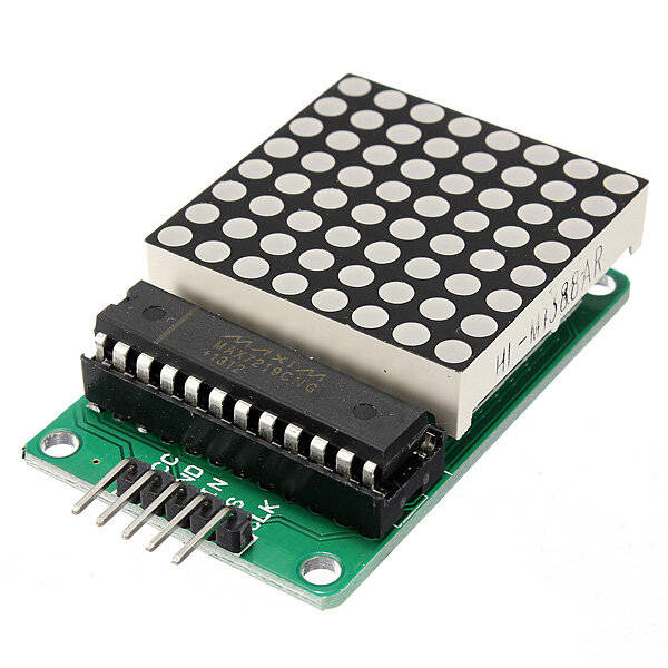
A single module can drive an 8 x 8 common cathode lattice
Operating voltage: 5V
Size: 5 x 3.2 x 1.5 cm (L x W x H)
LED color: red
With four screws hole, aperture 3mm
With input and output interfaces, supports multiple modules cascade

Wiring instructions:

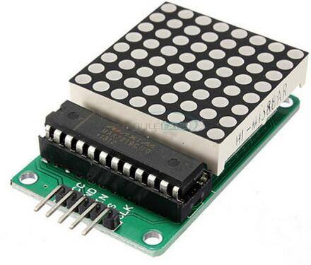
1. The module left side as an input port and the output port on the right
2. To control a single module, just connect the input port to the CPU
3. When cascading multiple modules, the input port of the first module connect to the CPU, the output port connect to the input port of the second one, and so on.

In the case of 51 MCU:

VCC → 5V
GND → GND
DIN → P22
CS → P21
CLK → P20

Note:

1. VCC and GND is not reversed, it would burn the chip!
2. When the 51 microcontroller P0 port controlling, must be connected to the pull-up resistor, it is recommended that the resistance of 4.7K--10K
3. Please install lattice into the round hole first, and then insert the round hole to PCB board and weld. Face the side of lattice with words, from left to right pin order is 123456. PCB board 1st pin is square pad!
4.Electrolytic capacitors long-pin as positive, short-pin as negative; ceramic capacitor hsa no positive and negative points

Package included:

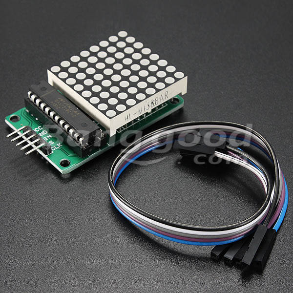
1 x LED module
5 x Dupont line (20cm)


,
Add to cart

Similar products