| Main centres: | 1-3 business days |
| Regional areas: | 3-4 business days |
| Remote areas: | 3-5 business days |
Specifications
| MODEL |
(This product) |
(Also available) | |
|---|---|---|---|
| MICROCONTROLLER | R7FA4 (32-bit ARM Cortex-M4) | R7FA4 (32-bit ARM Cortex-M4) | |
| ESP32-S3FN8 (Dual-core 32-bit Xtensa LX7) | |||
| CLOCK FREQUENCY | R7FA4: 48MHz | R7FA4: 48MHz | |
| ESP32-S3FN8: 240MHz | |||
| STORAGE | R7FA4: 256kB Flash, 32kB RAM | R7FA4: 256kB Flash, 32kB RAM | |
| ESP32-S3FN8: 384kB ROM, 512kB RAM, 8MB Flash | |||
| WIRELESS COMMUNICATION | None | 2.4GHz WiFi + Bluetooth LE | |
| OPERATING VOLTAGE | Options for 5V/3.3V, support more shields | ||
| POWER INPUT | 6~24V | ||
| RESET BUTTON | Lateral, easier to use when connecting with shield | ||
| IO PIN OUTPUT CURRENT | 8mA | ||
| DIGITAL PINS | 14 | ||
| ANALOG PINS | 6 | ||
| DAC | 2 | ||
| PWM | 6 | ||
| UART | 1 | ||
| I2C | 1 | ||
| SPI | 1 | ||
| CAN | 1 | ||
| DC JACK | Low profile, shields won't be blocked anymore while connecting | ||
| POWER OUTPUT HEADER | Provides 5V OR 3.3V power output and common-grounding with other boards | ||
| 5V POWER OUTPUT | Up to 2000mA Max, features higher driving capability | ||
| EXPERIMENTAL BOARD | Support, solder pad is provided for DIY interfaces to connect with experimental board | ||
Onboard 12×8 Red LED Matrix
Supports Customisation Of Display Effect

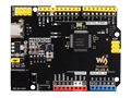
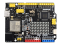
What's On Board?

Pinout Definition


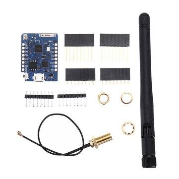
What's in the box?
1 x Arduino Uno Rev 4 wifi compatible
1 x USB Type-A to Type-C cable
Resources
Wiki: