Sound and Light Control Switch Kit Clap Switch Sound and Light Control Delay DIY Electronic Producti
Check my rate
| Main centres: | 1-3 business days |
| Regional areas: | 3-4 business days |
| Remote areas: | 3-5 business days |
Product details
Product manual:
Clap your hands and the LED lights up. After a while, the LED light goes off, then clap the LED light, and then it goes off, and so on.
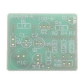
Circuit principle:
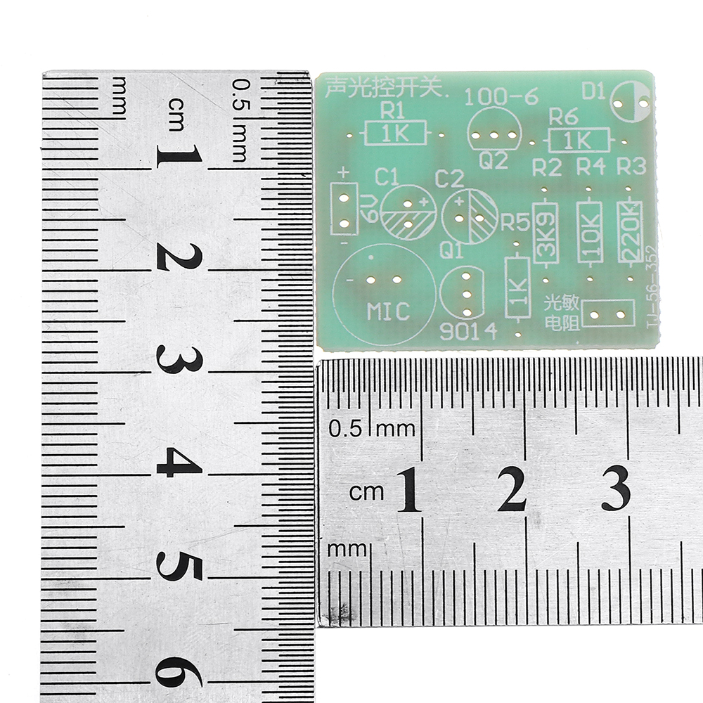
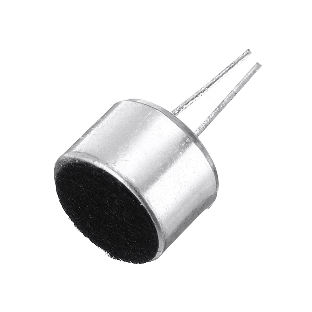
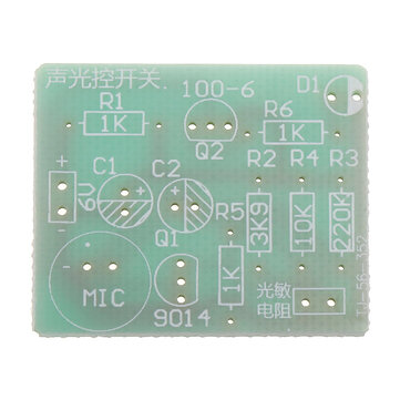
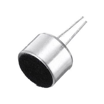
In the picture, GM is a photoresistor. During the daytime, it shows a low resistance state. At this time, the collector and the emitter of 9014 are equivalent to a short circuit. Whether it is screaming into the microphone or not, the gate of the thyristor MCR100-6 has been in a low power Flat, the thyristor is not conductive, and the light-emitting tube is not bright. At night (or cover the photoresistor with paper or other objects), the photoresistor shows a high resistance state, and the resistance between the GM resistors is very large at this time. When there is no sound, the triode is in a conducting state, the collector is low level, and the gate is also low level through R5, so the thyristor does not work at this time, and the light-emitting tube is not bright. At this time, speaking to the MIC microphone, the positive pole of the MIC will output a negative pulse. At this time, the positive charge of the capacitor C2 is instantly pulled away, and the negative pole of C2, that is, the base level of 9014 will become zero potential at the same time, and the transistor 9014 will change from on to After the cut-off, the collector changes from low level to high level, and the thyristor gate becomes conductive due to the high level. The light-emitting tube will light up, and the power supply will charge C2 through R3 to increase the base potential of 9014 until the transistor is turned on, the collector becomes low again, the thyristor is cut off, and the light-emitting tube is extinguished.
The lighting time of the light emitting tube depends on the size of R3 and C2.
Working voltage: 4.5-6V (4 AA dry batteries)
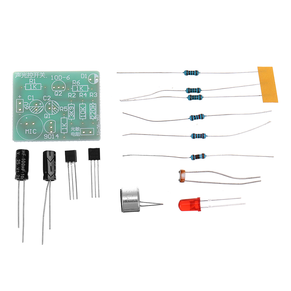
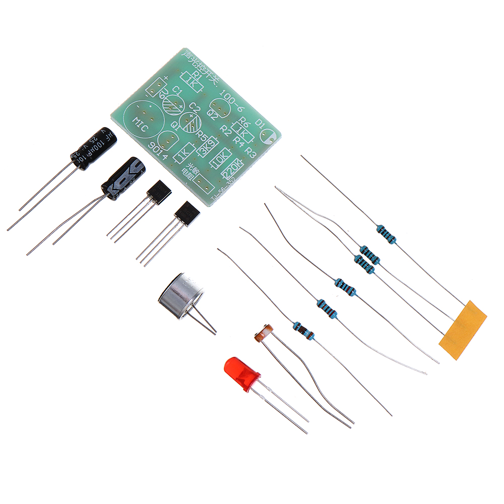
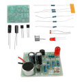
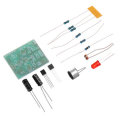
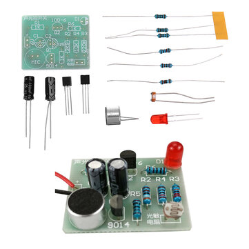
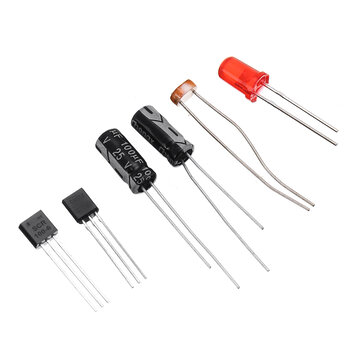
Package includes:
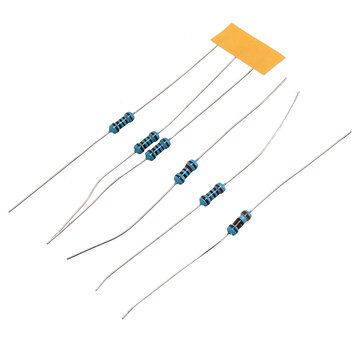
1 x diy kit