

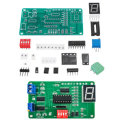
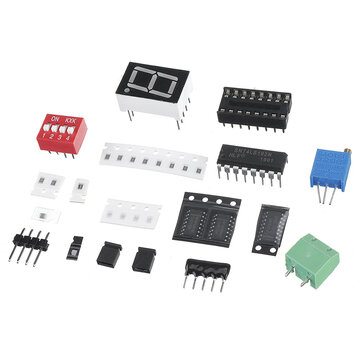
Subtraction Cycle Counter Circuit Kit 74LS192 Parts with Simulation Electronic DIY Training Kit
Check my rate
| Main centres: | 1-3 business days |
| Regional areas: | 3-4 business days |
| Remote areas: | 3-5 business days |
Product details
Feature:
Electronic kit for French cycle counter circuit. This circuit is a digital circuit composed of a signal generator, a NAND gate, a bidirectional counter, and a decoder. Through this circuit, you can understand the functions and usage of the NAND gate, counter, and decoder.
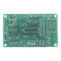
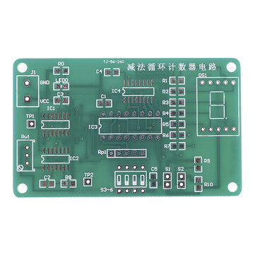
The kit is made of international standard plates, the pads are all tinned, high-strength fireproof and anti-fall materials, and can be disassembled repeatedly. The PCB board design is reasonable, and the commonly used chip components are used. Send information and simulation!
Board size: 75*46mm, board thickness: 1.6mm, circuit working voltage: 5V
Circuit description:
In the circuit, IC2A, IC2B and C2, R8, Rw1 form an oscillating circuit, which outputs a square wave signal. The frequency of the square wave can be adjusted by Rw1. When the power is just turned on, pin 1 and pin 2 of IC2A are high level and pin 3 is output. Low level, both sides of C2 without charge are low level, pin 5 and pin 6 of IC2B are also low level, pin 4 outputs high level, this high level voltage charges C2 through resistors Rw1 and R8, and the voltage on the right side of C2 gradually Rise, after a period of time, the voltage on the right side of C2 reaches the high level condition, pins 5 and 6 of IC2B become high level, pin 4 becomes low level output, and pins 1 and 2 connected between IC2A and pin 4 become low Flat, pin 3 outputs a high level, the voltage on the left side of C2 rises to a high level condition, the charge stored on C2 begins to pass R8, Rw1 is released to a low level, the voltage on the right side of C2 gradually decreases as the charge is released, when the voltage drops After reaching the low level condition, pins 5 and 6 of IC2B become low level, pin 4 outputs high level, pins 1 and 2 of IC2A become high level, pin 3 outputs low level, and starts charging C2 again In this way, a square wave signal is output during the oscillation process.
?
The square wave signal is shaped by IC1D. IC2D can be regarded as the switch of the square wave signal. The shaped signal is added to the subtraction counter 4 pin of 74LS192 bidirectional counter. S1 is the square wave signal input switch. When S1 is closed, the output of IC2D The terminal will remain high. Only when S1 is off, the square wave signal can reach the subtraction counter of 74LS192. S2 is used to reset the counter. When S2 is closed, the counter will no longer count in the reset state, and the count value returns to zero. The remaining NAND gates perform subtraction counting cycle control. When the counter counts to 0, the count value of 74LS192 changes from 0 to 9 when the next count signal arrives. At this time, pins 3 and 7 of 74LS192 become high. Level, make IC1A output low level, IC1B output high level is added to pin 8 of IC2C, the level of pin 9 of IC2C is determined by the state of the 4-bit DIP switch, when the value of the 4-bit DIP switch is not 9, IC1C outputs a high level. When the value of the 4-digit dial switch is 9, IC1C outputs a low level. In this way, when the count value of 74LS192 is 9, if the value of the dip switch is not 9, IC2C outputs a low level, and the counter loads the value of the dip switch into the counter. If the value of the dip switch = 9, IC2C maintains The high-level output remains unchanged, and the counter starts counting down from 9.
Package includes:
1 x DIY KIT


