| Main centres: | 1-3 business days |
| Regional areas: | 3-4 business days |
| Remote areas: | 3-5 business days |
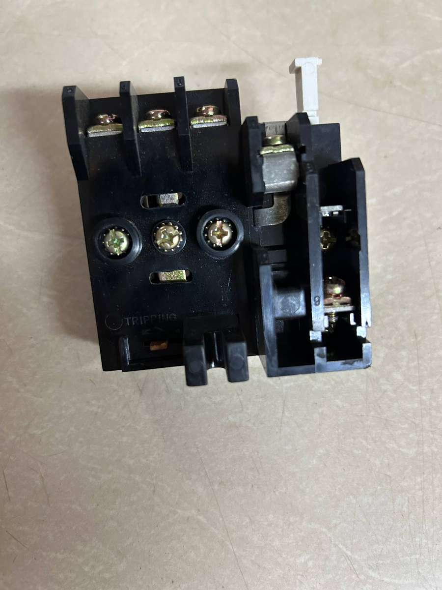
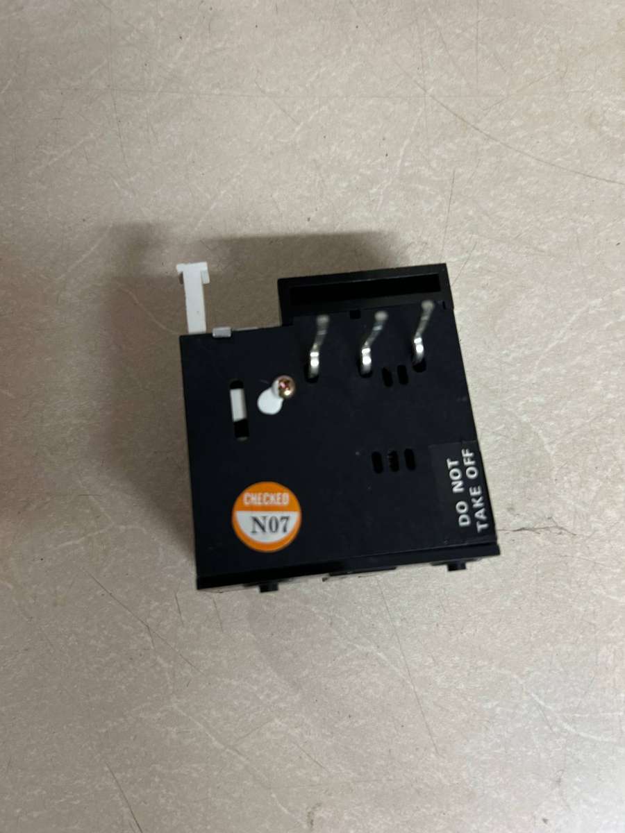
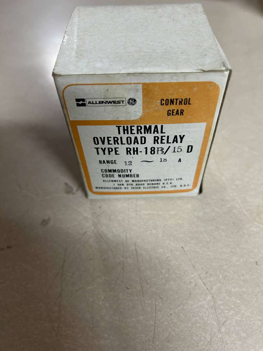
Ensure the longevity of your industrial machinery with high-end motor safety. This Allen West RH-18B/15D provides a robust defense against electrical faults, specifically tailored for demanding 3-phase environments.
Key Performance Specs
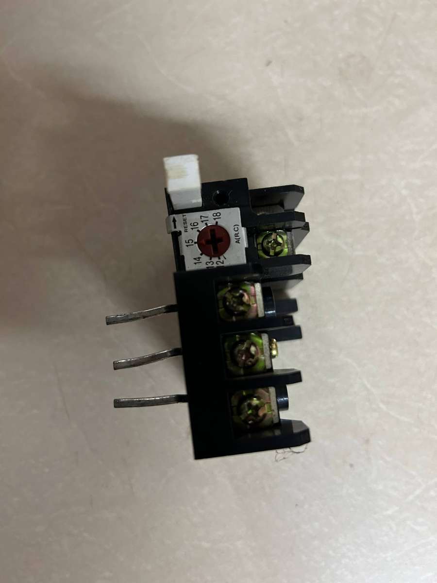
Adjustable Range: Precise current setting from 12A to 18A to match your motor's full load current.
Type: RH-18B / 15D Solid State/Thermal Relay.
Premium Protection: Advanced phase-failure detection and differential trip mechanisms to prevent burnout during unbalance.
Reset Flexibility: Includes both Hand (Manual) and Auto-reset modes with an integrated stop function for immediate control.
Built to Last: Durable, impact-resistant housing designed for direct mounting to Allen West Westmaster contactors.
Visual Diagnostics: High-visibility trip indicator for rapid troubleshooting and reduced downtime.
Applications
Ideal for protecting 7.5kW motors (at 400V) in pumps, compressors, and conveyor systems.
Installation of the Allen West RH-18B/15D thermal overload relay involves connecting it between a contactor and the motor to provide critical overload protection. The wiring configuration typically follows standard IEC or manufacturer-specific terminal layouts for power and control circuits.
ALLEN WEST RH-18B/15D THERMAL OVERLOAD RELAY
Power Circuit Wiring
The power terminals are used to pass the motor's full load current through the relay's thermal elements.
Input (L1, L2, L3): Connect the three-phase output terminals of your Allen West Westmaster contactor directly to the input pins or terminals of the relay.
Output (T1, T2, T3): Connect the three motor wires to the load terminals at the bottom of the relay.
Single-Phase Use: If using a three-phase relay for a single-phase motor, loop the wire back through all three phases (Series connection) to ensure the differential mechanism trips correctly.
Control Circuit Wiring
The control terminals act as a safety switch to kill power to the contactor's coil in the event of a fault.
NC Terminals (95 & 96): Wire the Normally Closed (NC) contact in series with the contactor coil (usually terminal A1). If an overload occurs, this contact opens, de-energizing the coil and stopping the motor.
NO Terminals (97 & 98): Use the Normally Open (NO) contact for an external alarm, light, or PLC signal to indicate a tripped state.
Configuration & Settings
Current Dial: Use a screwdriver to rotate the dial so the pointer matches the Full Load Amps (FLA) listed on your motor's nameplate.
Heater Packs: For older R Type models, ensure the internal heater packs are correctly seated and tightened to exactly 2.5mm above the molded platform as specified in technical manuals on Scribd.
Reset Mode: Select Hand (Manual) if you want to inspect the fault before restarting, or Auto for systems that can safely self-reset after cooling.