View the relisted Item
Similar products

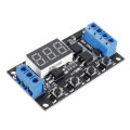
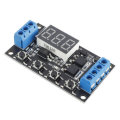
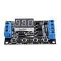
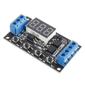
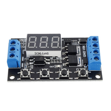
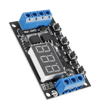
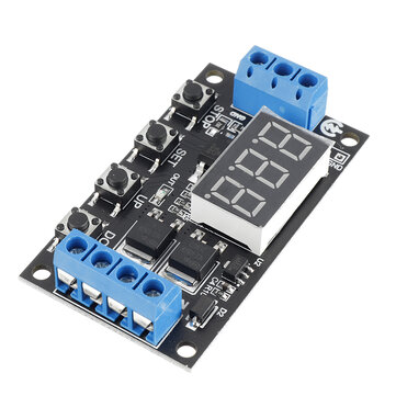
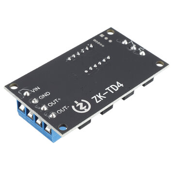
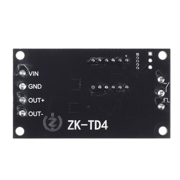
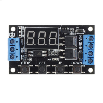
ZK-TD4 DC 5V 12V 24V Trigger Cycle Timer Delay Controller Module 15A 400W MOS Control Switch 16-Work
Check my rate
| Main centres: | 1-3 business days |
| Regional areas: | 3-4 business days |
| Remote areas: | 3-5 business days |
Product details
Description:
ZK-TD4 is a MOS Switch Controller Trigger Delay Module with Timer and Cycle functions.It can work in 16kind work mode with or without trigger signal.It also can be delay a random time in the set range. Features:
1.16kind work mode 2.High Level or PNP signal trigger 3.Power-ON trigger 4.Button switch trigger 5.400W 15A MOS Driver 6.Support parameter memory function 7.Support UART communication function 8.Optocoupler isolated output 9.Support forced stop function 10.Support power saving mode Parameters:
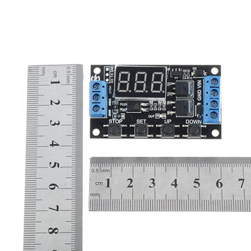
1.Product Name:ZK-TD4 Trigger Cycle Timer Delay Controller 2.Product Number:ZK-TD4 3.Working Voltage:DC 5.0V~30V 4.Trigger Type:Button/PNP/High Level Signal 5.Trigger Signal:DC 3.0V~24V 6.Output Type:Voltage Output(Same to input voltage) 7.Output Power:400W(Max) 8.Output Current:15A 9.Quiescent Current:20mA 10.Display: 3Bit Red LED Display Screen 11.Working Temperature range:-40?????~85????? 12.Working Humidity Range:5%-95%RH 13.Module Size:60*34*12mm Timing range:
1.Continuously adjustable from 0.1 seconds to 999 minutes. 2.Enter the settings interface when short press button STOP in the parameter modification interface(Flashing) to select timing range. 3.Pay attention to the position where the decimal point moves when the button is pressed. 4.Display XXX. The decimal point is the last bit, the timing range is 1 second ~ 999 seconds. 5.Display XX.X The decimal point is the second last,Timing range is 0.1 second to 99.9 seconds.
6.Display X.X.X. The decimal point is fully lit, timing range is 1 minute to 999 minutes. 7.For example, if you want to set the OP to 3.2 seconds, Screen will display 03.2 8.OP and CL parameters are the same in different work mode. 9.It will display OP(CL,LOP) and corresponding delay time by short press button SET in main display interface. 10.It just display OP and corresponding delay time in P1 mode by short press button SET in main display interface. Parameter Description:
1>.OP:Delay time for turn On; 2>.CL:Delay time Turn OFF; 3>.LOP:Number of cycles.Range is 1-999tims.---- means unlimited loop. 4>.CLL:Minimum value of random delay range. The set range is 0.0~99.9second. This CLL parameter just be used for P15 work mode. 5>.CLH:Maximum value of random delay range.The set range is 0.0~99.9second. This CLH parameter just be used for P15 work mode. 6>.SP:Set PWM duty cycle. The set range is 20%,25%,30%,35% to 100%. Work Mode:
1.Power-ON Trigger Mode: 1.1>.ZK-TD4 will start delay after power on. This mode no need input other trigger signal. The power supply is the trigger signal. 1.2>.P00: Power ON and output keep OFF and start delay time CL. Then turn ON output after delay time CL. E.g. Power ON->OFF->Delay CL->ON. 1.3>.P01: Power ON and output turn ON and start delay time OP. Then turn OFF output after delay time OP. E.g. Power ON->ON->Delay OP->OFF. 1.4>.P02: Power ON and output turn ON and start delay time OP. Then turn OFF output after delay time OP. Keep OFF for delay time CL. Then turn ON output after delay time OL. And then loops the above action.The number of cycles (LOP) can be set. Output will keep OFF after cycle. E.g. Power ON->ON->Delay OP->OFF->Delay CL->cycles->OFF. 1.5>.P03: Power ON and output turn OFF and start delay time CL. Then turn ON output after delay time CL. Keep ON for delay time OP. Then turn OFF output after delay time OP. And then loops the above action.The number of cycles (LOP) can be set. Output will keep ON after cycle. E.g. Power ON->OFF->Delay CL->ON->Delay OP->cycles->ON. 2.PNP/High Level Signal Trigger Mode: 2.1>.ZK-TD4 will start delay after input trigger. This mode need input trigger signal after provide work power supply. 2.2>.P04: Input trigger signal and output turn ON and start delay time OP. Then turn OFF output after delay time OP. Trigger again is invalid during delay.E.g. Trigger->ON->Delay OP->OFF. 2.3>.P05: Input trigger signal and output turn ON and start delay time OP. Then turn OFF output after delay time OP. Restart delay OP if trigger again during delay.E.g. Trigger->ON->Delay OP->OFF. 2.4>.P06: Input trigger signal and output turn ON and start delay time OP. Then turn OFF output after delay time OP. Stop delay and output turn OFF if trigger again during delay.E.g. Trigger->ON->Delay OP->OFF. 2.5>.P07: Input trigger signal and output keep OFF and start delay time CL. Then turn ON output after delay time CL. E.g. Trigger->OFF->Delay CL->ON. 2.6>.P08: Input trigger signal and output turn OFF and start delay time CL. Then turn ON output after delay time CL. Keep ON for delay time OP. Then turn OFF output after delay time OP. Trigger again is invalid during delay. E.g. Trigger->OFF->Delay CL->ON->Delay OP->OFF. 2.7>.P09: Input trigger signal and output turn OFF and start delay time CL. Then turn ON output after delay time CL. Keep ON for delay time OP. Then turn OFF output after delay time OP. Restart delay OP if trigger again during delay. E.g. Trigger->OFF->Delay CL->ON->Delay OP->OFF. 2.8>.P10: Input trigger signal and output turn OFF and start delay time CL. Then turn ON output after delay time CL. Keep ON for delay time OP. Then turn OFF output after delay time OP. And then loops the above action.The number of cycles (LOP) can be set. Output will keep ON after cycle.Stop delay and output turn ON if trigger again during cycles. E.g. Trigger->OFF->Delay CL->ON->Delay OP->cycles->ON. 2.9>.P11: Input trigger signal and output turn ON and start delay time OP. Then turn OFF output after delay time OP. Keep OFF for delay time CL. Then turn ON output after delay time CL. And then loops the above action.The number of cycles (LOP) can be set. Output will keep OFF after cycle.Stop delay and output turn OFF if trigger again during cycles. E.g. Trigger->ON->Delay OP->OFF->Delay CL->cycles->OFF. 2.10>.P12: Input trigger signal and output turn ON and start delay time OP. Then turn OFF output after delay time OP. Keep OFF for delay time CL. Then turn ON output after delay time CL. And then loops the above action.The number of cycles (LOP) can be set. Output will keep OFF after cycle.Trigger again is invalid during cycles. E.g. Trigger->ON->Delay OP->OFF->Delay CL->cycles->OFF. 2.11>.P13: Keep input trigger signal and output turn ON.Then start delay time OP if remove input trigger.Then turn OFF output after delay time OP.Stop delay and output turn ON if trigger again during delay. 2.12>.P14: Keep input trigger signal and output turn OFF.Then start delay time CL if remove input trigger.Then turn ON output after delay time CL.Stop delay and output turn OFF if trigger again during delay. 3.Random Delay Mode: 3.1>.P15: Input trigger signal and output keep OFF and start delay time. The delay time between CLL and CLH. Then turn ON output after delay time CLL~CLH.This mode also can set PWM duty cycle from 20%,25%,30%,35% to 100%. (The delay time is a random value between CLL and CLH. Their setting range is 0.0~99.9second and CLH is more than CLL.) E.g. Trigger->OFF->Delay->ON. Set steps: