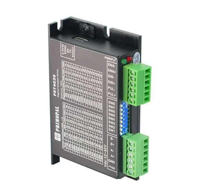
R35.00 Standard shipping using one of our trusted couriers applies to most areas in South Africa. Some areas may attract a R30.00 surcharge. This will be calculated at checkout if applicable. Check my rate
The seller has indicated that they will usually have this item
ready to ship within 3 business days.
Shipping time depends on your delivery address.
The most accurate delivery time will be calculated at checkout,
but in general, the following shipping times apply:
Warranty Type: Manufacturer
https://acrobat.adobe.com/id/urn:aaid:sc:EU:60f589d9-954e-4367-b1cd-895555c7a9d4
Money-Back Guarantee:
7 Days: Money back in 7 days and replacement
Get it now, pay later
Product details
Condition
New
Location
South Africa
Product code
MOT-0034
Bob Shop ID
641218071
The PST4030 is a versatility fully digital stepping driver based on ARM with advanced control algorithm. The PST4030 is the next generation of digital stepping motor controls. It brings a unique level of system smoothness, providing optimum torque and nulls mid-range instability. Motor self-test and parameter auto-setup technology offers optimum responses with different motors and easy-to-use. The driven motors can run with much smaller noise, lower heating, smoother movement than most of the drivers in the markets. Its unique features make the PST4030 an ideal solution for applications that require low-speed smoothness.
The stepper drive PST4030 is suitable for a wide range of stepping motors from NEMA size 8 to 17, which are used in various kinds of machines, such as 3D printers, X-Y tables, labeling machines, laser cutters, engraving machines, pick-place devices,
and etc
Electrical Specifications:
Output current:
Min: 0.14
Max: 3.0 (2.2RMS)
Unit: A
Supply voltage:
Min: +12
Typical: +24
Max: +32
Unit: VDC
Logic signal current:
Min: 6
Typical: 10
Max: 16
Unit: mA
Pulse input frequency:
Min: 0
Max: 160
Unit: kHz
Isolation resistance:
Min: 500
Unit: MOHM
Function Description:
Micro step Setting: Micro step resolution is programmable. When not in software configured mode, micro step resolution is set by SW5, 6, 7, 8 of the DIP switch. In order to avoid losing steps, do not change the micro step resolution on the fly.
Current Setting: Output current is programmable. When not in software configured mode, operating current is set by SW1, 2, 3, 4 of the DIP switch, which is Up to 3.0A.
Automatic Standstill Current Reduction: The current will be automatically reduced to 50% of the selected operating current 0.4 second after the last pulse.
Control Signals: PUL+ and PUL- are for the pulse command signal. DIR+ and DIR- are for the direction control signal. ENA+ and ENA are for the enable/disable control signal.
Motor Connector: A+, A- and B+, B- are for motor connections. Exchanging the connection of two wires for a coil to the drive will reverse default motion direction.
Power Connector: Recommended to use power supplies with output of +20 to 45VDC, leaving space for power fluctuation and back-EMF.
Indicators: There are two LED indicators on the drive for power and alarm signals. When the Green LED is on, the drive is powered up. When the Red LED is on, the drive is in fault status. When in fault status, the motor shaft will be free. Reset the drive by repowering it to make it function properly after solving problem(s).