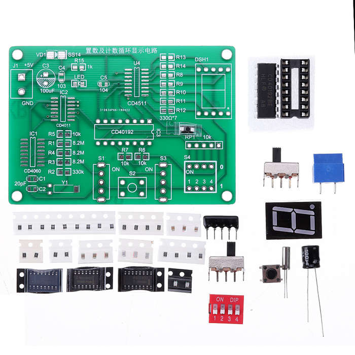
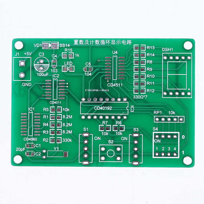
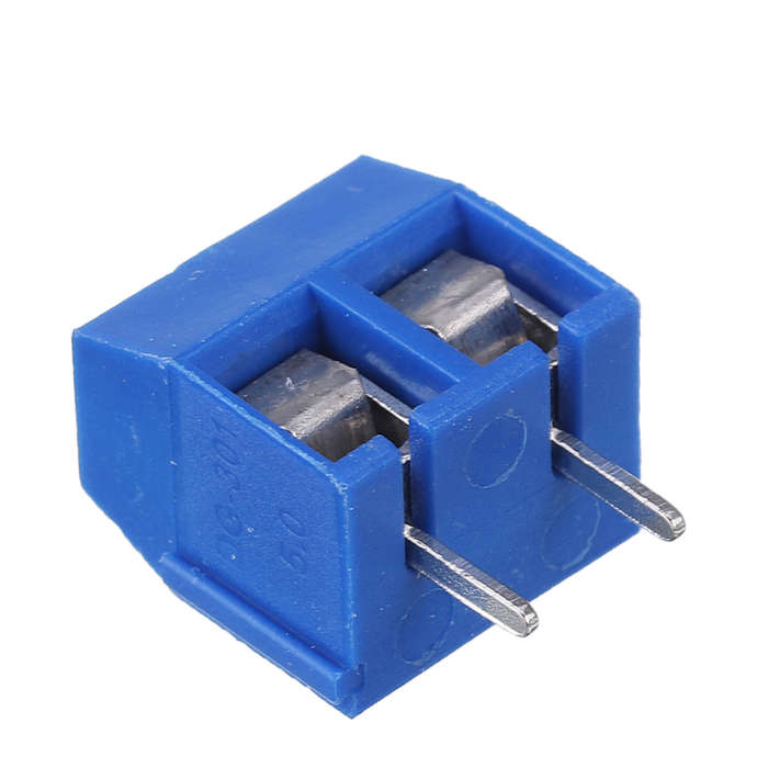
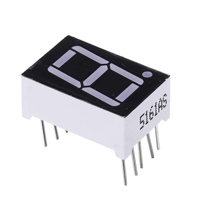
Circuit function introduction: Connect + 5V DC voltage to J1, the power indicator LED is on, and the digital tube DSH1 displays 0.
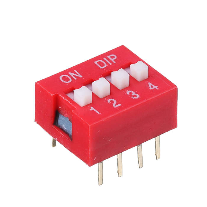
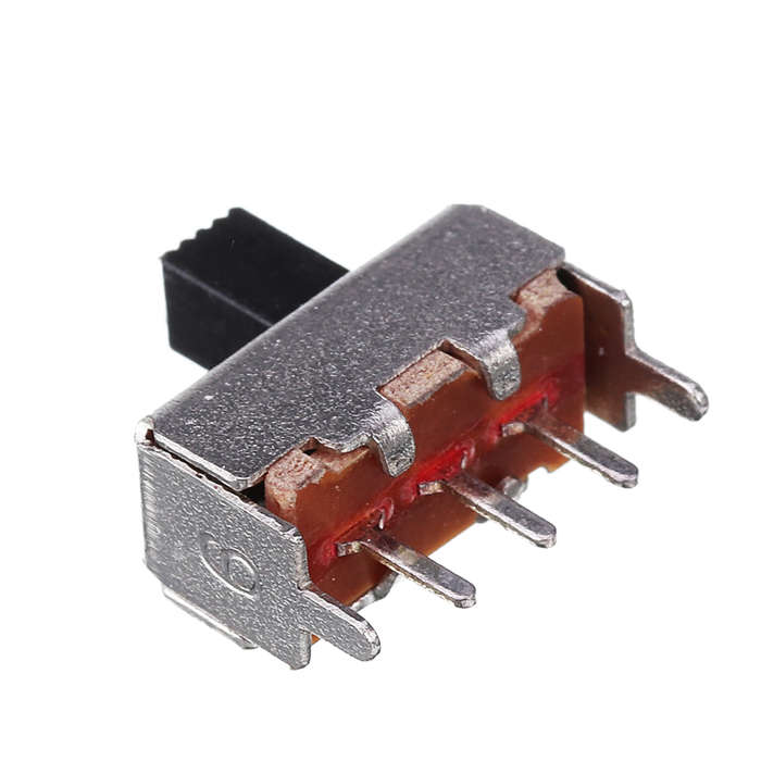
Switch S3 is set to the ON position. DIP switch S4 operates as follows: A. Turn off the 1 switch and the other on, press the micro switch S2, the digital tube DSH1 displays 1, and release the micro button S2, the digital tube display returns to 0.
B. Switch 2 is off, the other is on, press the micro switch S2, the digital tube DSH1 displays 2, and release the micro button S2, the digital tube display returns to 0.
C. Turn off the 4 switch, and other switches on. Press the micro switch S2, the digital tube DSH1 displays 4, and release the micro button S2, the digital tube display returns to 0.
D. Switch 8 is off, the other is on, press the micro switch S2, the digital tube DSH1 displays 8, and release the micro button S2, the digital tube display returns to 0.
E. Press the DIP switch S4 (1 ~ 4 switches) according to the number 0-9 coding (ON is 0), press the jog button S2, the digital tube DSH1 displays the number according to the code, release
Press the S2 key, and the digital tube display returns to 0.
Set switch S3 to the off position:
Switch S1 is set to the off position. Pressing the jog button S2, the digital tube DSH1 displays the number starting from 0. Every XXS seconds, the number displayed by the digital tube increases by 1, that is, from 0 to 9, and continues to cycle. No matter what number is displayed on the nixie tube, release the S2 button, and the number displayed on the nixie tube returns to 0.
Switch S1 is set to the ON position. Pressing the jog button S2, the digital tube DSH1 displays the number starting from 0. Every XXS seconds, the number displayed by the digital tube decreases by 1, that is, from 9 to 0, and continues to cycle. No matter what number is displayed on the nixie tube, release the S2 button, and the number displayed on the nixie tube returns to 0.
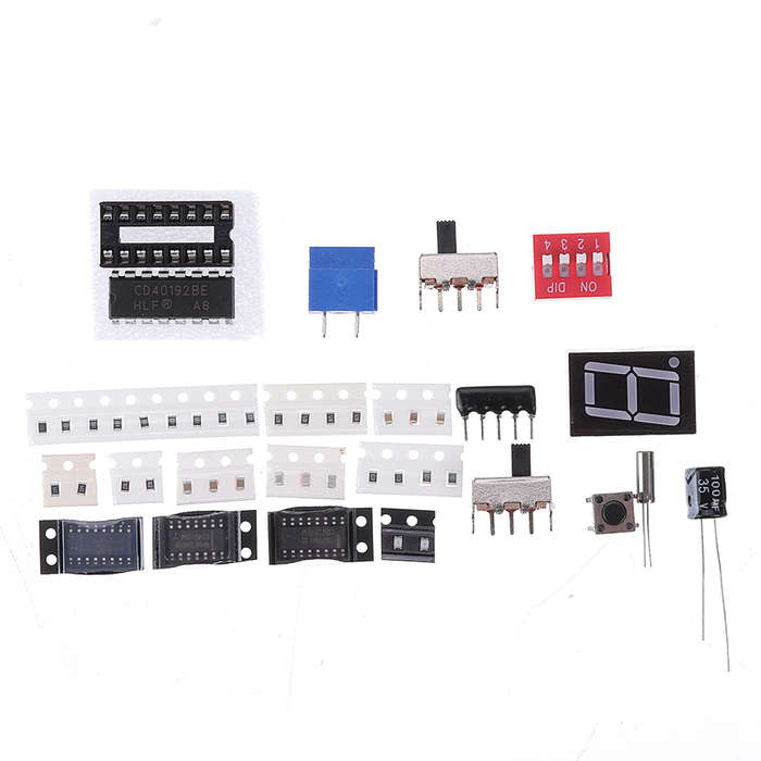
Package included: 1 x Setting and Counting Cycle Display Circuit Board DIY Kit