R35.00 Standard shipping using one of our trusted couriers applies to most areas in South Africa. Some areas may attract a R30.00 surcharge. This will be calculated at checkout if applicable. Check my rate
The seller has indicated that they will usually have this item
ready to ship within 12 business days.
Shipping time depends on your delivery address.
The most accurate delivery time will be calculated at checkout,
but in general, the following shipping times apply:
Replacement Guarantee:
7 Days: We stand by this guarantee
Get it now, pay later
Product details
Condition
New
Location
International
Bob Shop ID
640901225
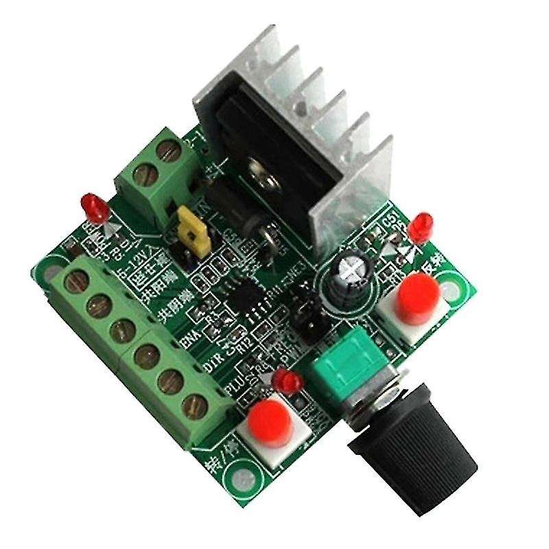
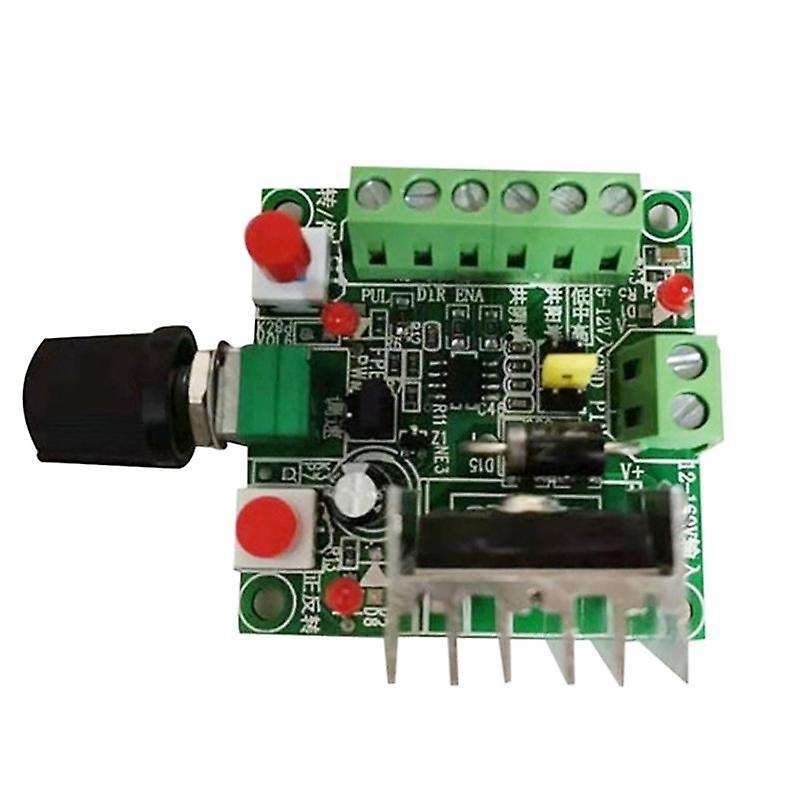
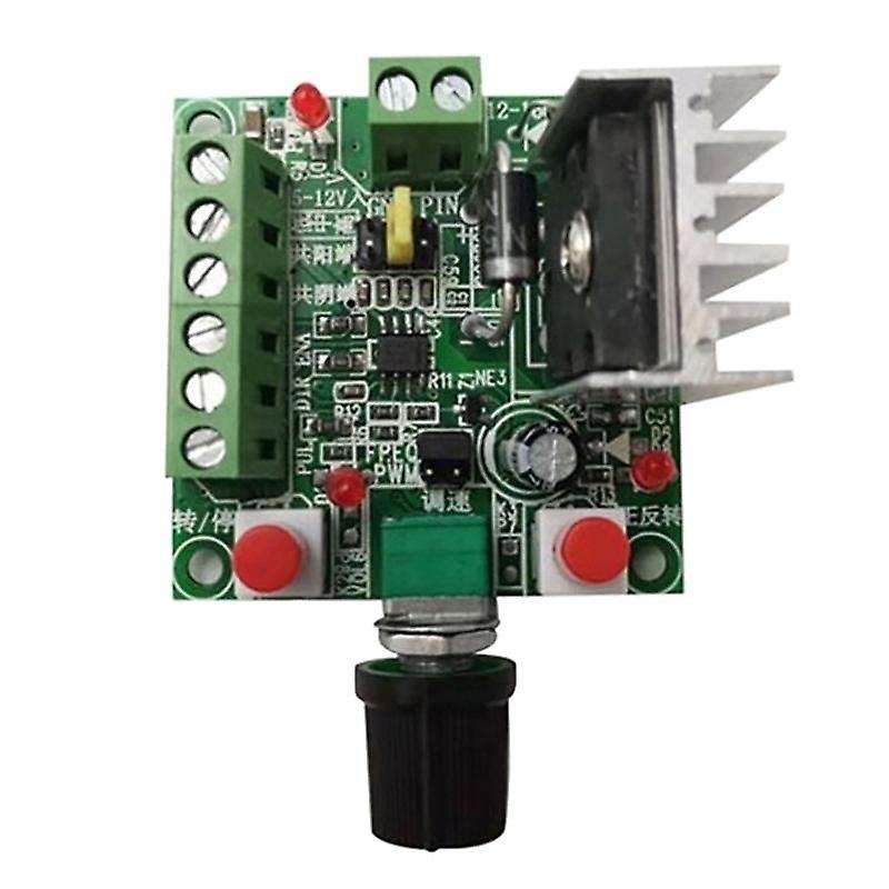
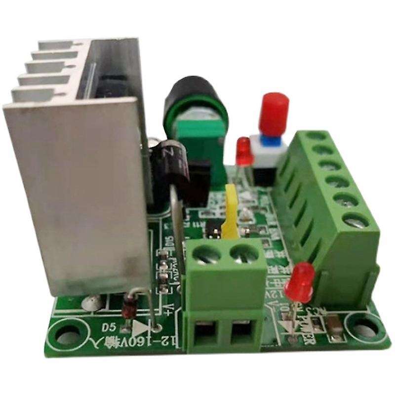
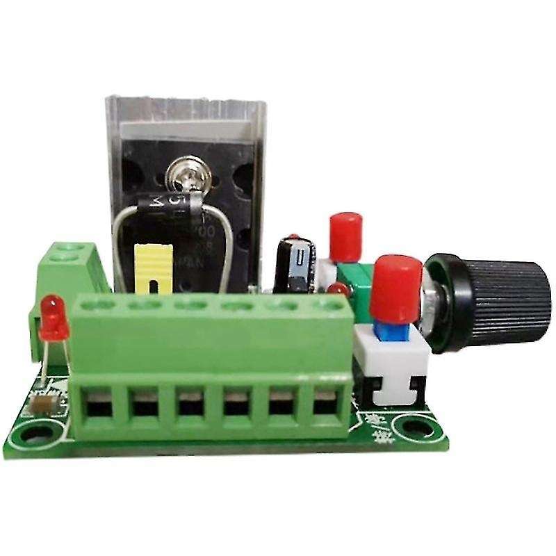
1. When the controller generates a pulse frequency signal, it can be supplied to the stepper driver as a signal. If you want to control the stepper motor, it must also be equipped with a driver. This simple controller + stepper driver + stepper motor + DC power supply can form a simple control platform.2. The controller can generate pulse frequency signal and PWM pulse width signal. There is a jumper on the board, which can be set and selected. By default, it is set to generate pulse frequency signals. REQ is to generate a pulse frequency signal. PWM is to generate PWM signal3. When the controller generates a pulse frequency signal, there are three frequency signals of high, medium and low, which can be selected by the jumper. The frequency parameters are about: High: 5.8KHZ-127KHZ; Middle: 590HZ-15.8KHZ; Low: 82HZ-2.3KHZ, Frequency measurement: PUL and common cathode (GND) ports can be measured.4. There are 2 groups of power input for power supply, and 2 groups only need to be connected to one group of power supplies. It is recommended to use a power supply above 15V. Connect to the power supply of the 2-position terminal, and do not reverse the positive and negative.One group is the power supply connected to DC 15-160VDC, and the recommended working voltage is 15-80VDC.The other group is 5-12VDC. When used with the driver, it is recommended to use a minimum of 12V, do not use a 5V power supply for power supply, it is not too much at 5V, the power supply is connected to 5-12V input, and the negative power supply is connected to common cathode.2. Wiring instructions1. for the wiring of each wiring port, there are silkscreen instructions next to the terminals. Common cathode or common anode can be connected to the stepper motor driver.PUL: Pulse portDIR: Direction portENA: enable portCommoncathode: common ground (GND)Common anode terminal: common terminal (+5V)5-12V power supply is positive: the positive terminal of 12V power supply is generally empty, it is recommended to use a power supply above 15V.Material: PCBcolour: As shownPackage Contents:1 x Stepper Motor ControllerOnly the above package content, other products are not included.Note: Light shooting and different displays may cause the color of the item in the picture a little different from the real thing. The measurement allowed error is +/- 1-3cm.